> ## Documentation Index
> Fetch the complete documentation index at: https://dragonwingdocs.qualcomm.com/llms.txt
> Use this file to discover all available pages before exploring further.
# I3C
The Improved Inter-Integrated Circuit (I3C) interface provides a fast, low-cost, low-power, 2-wire digital interface for connected I3C devices.
I3C is supported for **aDSP sensor communication only**. It is not supported for Linux use cases.
## Overview
### Bus Characteristics
* 2-wire serial interface (SDA + SCL) supporting up to 12.5 MHz
* Backward compatible with legacy I2C devices on the same bus
* Address phase: 400 kHz
* Data phase: 12.5 MHz
### Advanced Features
* In-band interrupt (IBI) support
* Hot-join (dynamic device addition)
* Synchronous timing and asynchronous timestamping
* 8-bit data parity during write operations
* Dynamic addressing of targets
* Single Data Rate (SDR) mode
* CCC (Common Command Codes) per MIPI I3C specification
### Data Phase Modes
| Mode | Usage |
| -------------- | -------------------------- |
| **Push-pull** | I3C-capable devices |
| **Open-drain** | Mixed bus with I2C devices |
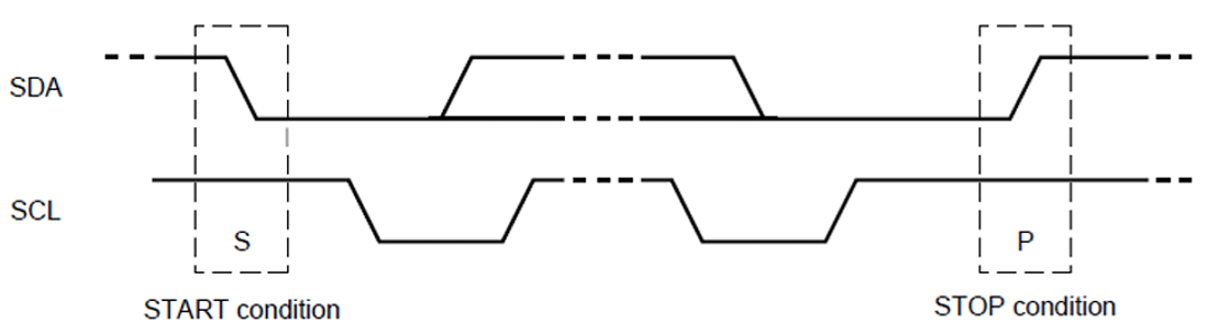 ## Packet Frame Structure
| Component | Description |
| ----------------------- | ------------------------------------------------- |
| **S / Sr** | Start or Repeat Start condition |
| **I3C Dynamic Address** | 7-bit dynamic address assigned during enumeration |
| **R/W** | Direction bit (1=Read, 0=Write) |
| **ACK** | Acknowledge (SDA low) |
| **Data** | 8-bit data payload |
| **T** | Transition bit (alternative to ACK/NACK) |
| **P** | Stop condition |
## Bus Initialization
The I3C controller driver initializes the controller, including firmware loading and configuration settings.
The driver reads the I3C configuration and device database:
* List of I2C static address devices
* List of I3C static address devices
* Expected I3C dynamic devices (vendor ID, device ID, predefined dynamic address, associated drivers)
* Optional hot-join allowed devices
The driver enumerates devices on the bus and assigns local addresses.
The driver writes bus configuration to the controller:
* Operation frequency
* Pure/legacy I2C mode
* SDR/HDR enable/disable
* IBI-capable devices and expected data bytes
Client software receives the device list and configuration for I2C/I3C devices and hot-join devices.
## Software Configuration
### Firmware Loading
I3C firmware for the QUP v3 serial engine loads with SSC QUP during aDSP bootup.
**Configuration files:**
```
/ADSP.HT.5.5.c8/adsp_proc/core/settings/buses/qup_fw/config//fw_devcfg.c
/ADSP.HT.5.5.c8/adsp_proc/core/settings/buses/qup_fw/config//fw_devcfg.xml
```
**Serial engine configuration example:**
```c theme={null}
se_cfg se0_cfg = { 0x80000, SE_PROTOCOL_I3C, GSI, TRUE, TRUE };
se_cfg se1_cfg = { 0x84000, SE_PROTOCOL_I3C, GSI, TRUE, TRUE };
```
### GPIO Configuration
```c theme={null}
{
.instance_id = 1,
.qup = QUP_SSC,
.se_index = 0,
.protocol_io_cfg = {
TLMM_MAP(TLMM_GPIO_KEEPER, TLMM_GPIO_2MA, TLMM_GPIO_KEEPER), // SLEEP
TLMM_MAP(TLMM_GPIO_NO_PULL, TLMM_GPIO_6MA, TLMM_GPIO_KEEPER), // SPI
TLMM_MAP(TLMM_GPIO_NO_PULL, TLMM_GPIO_2MA, TLMM_GPIO_NO_PULL), // UART
TLMM_MAP(TLMM_GPIO_PULL_UP, TLMM_GPIO_2MA, TLMM_GPIO_NO_PULL), // I2C
TLMM_MAP(TLMM_GPIO_PULL_UP, TLMM_GPIO_2MA, TLMM_GPIO_KEEPER) // I3C
},
.se_exclusive = TRUE,
}
```
## Troubleshooting
* Verify SDA/SCL connections and pull-up resistors (1–4.7 kΩ)
* Confirm vendor ID and device ID match expected values
Verify SCL frequency is 400 kHz during address phase. Adjust clock divider settings in firmware configuration.
* Verify hot-join is enabled in configuration
* Add device to the hot-join allowed list (vendor ID + device ID)
* Measure rise/fall times on SDA and SCL
* Adjust pull-up resistor values
* Reduce bus length or capacitance
### Common Error Codes
| Error | Description | Solution |
| ----------- | ---------------- | ------------------------------------ |
| `ENXIO` | Device not found | Verify connection and enumeration |
| `ETIMEDOUT` | Transfer timeout | Check clock signals and device power |
| `EIO` | I/O error | Check signal quality and pull-ups |
| `EPROTO` | Protocol error | Verify timing parameters |
## Resources
* MIPI I3C Specification
* Qualcomm Linux Interfaces Guide
* QUP v3 Serial Engine Documentation
## Packet Frame Structure
| Component | Description |
| ----------------------- | ------------------------------------------------- |
| **S / Sr** | Start or Repeat Start condition |
| **I3C Dynamic Address** | 7-bit dynamic address assigned during enumeration |
| **R/W** | Direction bit (1=Read, 0=Write) |
| **ACK** | Acknowledge (SDA low) |
| **Data** | 8-bit data payload |
| **T** | Transition bit (alternative to ACK/NACK) |
| **P** | Stop condition |
## Bus Initialization
The I3C controller driver initializes the controller, including firmware loading and configuration settings.
The driver reads the I3C configuration and device database:
* List of I2C static address devices
* List of I3C static address devices
* Expected I3C dynamic devices (vendor ID, device ID, predefined dynamic address, associated drivers)
* Optional hot-join allowed devices
The driver enumerates devices on the bus and assigns local addresses.
The driver writes bus configuration to the controller:
* Operation frequency
* Pure/legacy I2C mode
* SDR/HDR enable/disable
* IBI-capable devices and expected data bytes
Client software receives the device list and configuration for I2C/I3C devices and hot-join devices.
## Software Configuration
### Firmware Loading
I3C firmware for the QUP v3 serial engine loads with SSC QUP during aDSP bootup.
**Configuration files:**
```
/ADSP.HT.5.5.c8/adsp_proc/core/settings/buses/qup_fw/config//fw_devcfg.c
/ADSP.HT.5.5.c8/adsp_proc/core/settings/buses/qup_fw/config//fw_devcfg.xml
```
**Serial engine configuration example:**
```c theme={null}
se_cfg se0_cfg = { 0x80000, SE_PROTOCOL_I3C, GSI, TRUE, TRUE };
se_cfg se1_cfg = { 0x84000, SE_PROTOCOL_I3C, GSI, TRUE, TRUE };
```
### GPIO Configuration
```c theme={null}
{
.instance_id = 1,
.qup = QUP_SSC,
.se_index = 0,
.protocol_io_cfg = {
TLMM_MAP(TLMM_GPIO_KEEPER, TLMM_GPIO_2MA, TLMM_GPIO_KEEPER), // SLEEP
TLMM_MAP(TLMM_GPIO_NO_PULL, TLMM_GPIO_6MA, TLMM_GPIO_KEEPER), // SPI
TLMM_MAP(TLMM_GPIO_NO_PULL, TLMM_GPIO_2MA, TLMM_GPIO_NO_PULL), // UART
TLMM_MAP(TLMM_GPIO_PULL_UP, TLMM_GPIO_2MA, TLMM_GPIO_NO_PULL), // I2C
TLMM_MAP(TLMM_GPIO_PULL_UP, TLMM_GPIO_2MA, TLMM_GPIO_KEEPER) // I3C
},
.se_exclusive = TRUE,
}
```
## Troubleshooting
* Verify SDA/SCL connections and pull-up resistors (1–4.7 kΩ)
* Confirm vendor ID and device ID match expected values
Verify SCL frequency is 400 kHz during address phase. Adjust clock divider settings in firmware configuration.
* Verify hot-join is enabled in configuration
* Add device to the hot-join allowed list (vendor ID + device ID)
* Measure rise/fall times on SDA and SCL
* Adjust pull-up resistor values
* Reduce bus length or capacitance
### Common Error Codes
| Error | Description | Solution |
| ----------- | ---------------- | ------------------------------------ |
| `ENXIO` | Device not found | Verify connection and enumeration |
| `ETIMEDOUT` | Transfer timeout | Check clock signals and device power |
| `EIO` | I/O error | Check signal quality and pull-ups |
| `EPROTO` | Protocol error | Verify timing parameters |
## Resources
* MIPI I3C Specification
* Qualcomm Linux Interfaces Guide
* QUP v3 Serial Engine Documentation