> ## Documentation Index
> Fetch the complete documentation index at: https://dragonwingdocs.qualcomm.com/llms.txt
> Use this file to discover all available pages before exploring further.
# 40 Pin Low Speed Connector
The Dragonwing IQ9-EVK contains one low-speed connector (JLS1) that provides access to various GPIOs, CAN, QUPs, and other interfaces.
## Pinout
The figure below shows the default functions of the IQ-9075 EVK 40-pin LS connector.

 ## GPIOs
The following commands require root privileges. Use `sudo su` to switch to the root user.
### Identify GPIO Subsystem Numbers
Identify the base GPIO number by running the following command and looking for `platform/f000000.pinctrl` (gpiochip4).
```text theme={null}
mount -t debugfs none /sys/kernel/debug/
cat /sys/kernel/debug/gpio
```
## GPIOs
The following commands require root privileges. Use `sudo su` to switch to the root user.
### Identify GPIO Subsystem Numbers
Identify the base GPIO number by running the following command and looking for `platform/f000000.pinctrl` (gpiochip4).
```text theme={null}
mount -t debugfs none /sys/kernel/debug/
cat /sys/kernel/debug/gpio
```
| LS1 Connector GPIO |
| GPIO |
Odd |
Even |
GPIO |
| GND | 1 | 2 | GND |
| 52 | 3 | 4 | CAN\_H |
| 54 | 5 | 6 | CAN\_L |
| 55 | 7 | 8 | 32 |
| 53 | 9 | 10 | 33 |
| 44 | 11 | 12 | 34 |
| 45 | 13 | 14 | 35 |
| 96 | 15 | 16 | 107 |
| 95 | 17 | 18 | 106 |
| 100 | 19 | 20 | 109 |
| 99 | 21 | 22 | 108 |
| 40 | 23 | 24 | 105 |
| 41 | 25 | 26 | 43 |
| 42 | 27 | 28 | SAIL59 |
| PME 11 | 29 | 30 | SAIL42 |
| 140 | 31 | 32 | SAIL46 |
| IO EXP3 7 | 33 | 34 | SAIL50 |
| 3.3V | 35 | 36 | SYS PWR |
| 5V | 37 | 38 | SYS PWR |
| GND | 39 | 40 | GND |
# Configure GPIOs from User Space
Use the `libgpiod` library from user space to control the GPIOs for better performance.
```bash theme={null}
sudo apt install gcc-aarch64-linux-gnu
sudo apt install binutils-aarch64-linux-gnu
```
```bash theme={null}
wget https://www.kernel.org/pub/software/libs/libgpiod/libgpiod-1.6.4.tar.xz
tar xvf libgpiod-1.6.4.tar.xz
cd libgpiod-1.6.4
```
```bash theme={null}
./configure --enable-tools=yes --build x86_64-pc-linux-gnu --host aarch64-linux-gnu CFLAGS="-static -static-libgcc -Wl,-static,--start-group,/usr/lib/gcc-cross/aarch64-linux-gnu/7.5.0/libgcc.a,/usr/lib/gcc-cross/aarch64-linux-gnu/7.5.0/libgcc_eh.a,/usr/aarch64-linux-gnu/lib/libc.a,--end-group"
```
```bash theme={null}
make
```
Compiling creates linked binaries.
```bash theme={null}
aarch64-linux-gnu-gcc -static -o tools/gpiodetect tools/gpiodetect.o tools/tools-common.o -Wl,-L<ABSOLUTE_PATH_TO_LIBGPIOD>/libgpiod-1.6.4/lib/.libs,-lgpiod,-lpthread,-static
aarch64-linux-gnu-gcc -static -o tools/gpioget tools/gpioget.o tools/tools-common.o -Wl,-L<ABSOLUTE_PATH_TO_LIBGPIOD>/libgpiod-1.6.4/lib/.libs,-lgpiod,-lpthread,-static
aarch64-linux-gnu-gcc -static -o tools/gpioset tools/gpioset.o tools/tools-common.o -Wl,-L<ABSOLUTE_PATH_TO_LIBGPIOD>/libgpiod-1.6.4/lib/.libs,-lgpiod,-lpthread,-static
aarch64-linux-gnu-gcc -static -o tools/gpiofind tools/gpiofind.o tools/tools-common.o -Wl,-L<ABSOLUTE_PATH_TO_LIBGPIOD>/libgpiod-1.6.4/lib/.libs,-lgpiod,-lpthread,-static
aarch64-linux-gnu-gcc -static -o tools/gpioinfo tools/gpioinfo.o tools/tools-common.o -Wl,-L<ABSOLUTE_PATH_TO_LIBGPIOD>/libgpiod-1.6.4/lib/.libs,-lgpiod,-lpthread,-static
aarch64-linux-gnu-gcc -static -o tools/gpiomon tools/gpiomon.o tools/tools-common.o -Wl,-L<ABSOLUTE_PATH_TO_LIBGPIOD>/libgpiod-1.6.4/lib/.libs,-lgpiod,-lpthread,-static
```
```bash theme={null}
scp gpiodetect gpioget gpioset gpiofind gpioinfo root@:/path/to/directory/on/device
```
Run `gpiodetect` to list the GPIO chips.
```bash theme={null}
./gpiodetect
```
Example output:
```text theme={null}
gpiochip0 [c440000.spmi:pmic@8:pinctrl@c00] (12 lines)
gpiochip1 [c440000.spmi:pmic@1:gpio@8800] (10 lines)
gpiochip2 [c440000.spmi:pmic@2:gpio@8800] (9 lines)
gpiochip3 [c440000.spmi:pmic@0:gpio@b000] (4 lines)
gpiochip4 [f100000.pinctrl] (176 lines)
gpiochip5 [33c0000.pinctrl] (15 lines)
```
Run `gpioinfo` to view the lines for a specific chip.
```text theme={null}
./gpioinfo gpiochip4
```
Example output:
```text theme={null}
gpiochip4 - 151 lines:
line 0: unnamed "?" input active-high [used]
line 1: unnamed unused input active-high
line 2: unnamed "perst" output active-low [used]
line 3: unnamed unused input active-high
line 4: unnamed "perst" output active-low [used]
line 5: unnamed "?" input active-high [used]
line 6: unnamed unused input active-high
line 7: unnamed unused input active-high
line 8: unnamed unused input active-high
line 9: unnamed unused input active-high
line 10: unnamed unused input active-high
line 11: unnamed unused input active-high
line 12: unnamed unused input active-high
line 13: unnamed unused input active-high
line 14: unnamed unused input active-high
line 15: unnamed unused input active-high
......
.....
```
To set GPIO line `54` on `gpiochip4`, run:
```text theme={null}
./gpioset gpiochip4 54=1
./gpioinfo gpiochip4 | grep 54
```
Example output:
```text theme={null}
gpiochip4 - 176 lines:
line 54: unnamed unused output active-high
```
To read GPIO line `0` on `gpiochip4`, run:
```text theme={null}
./gpioget gpiochip4 0
```
Example output:
```text theme={null}
1
```
After reading the value, `gpioinfo` shows the line returned to input mode.
```text theme={null}
./gpioinfo gpiochip4
```
Example output:
```text theme={null}
gpiochip4 - 176 lines:
line 0: unnamed unused input active-high
line 1: unnamed unused input active-high
```
## UART
Pins 5 and 7 are configured for UART by default (GPIO lines 54 and 55, mapping to `uart12 = qup1_se5 (0xa98000)`).
Follow the [Modify serial engine node](./peripheral_interface_overview#modify-serial-engine-node) procedure to enable the UART interface. After enabling, the device node appears at `/dev/ttyHS3`.
```bash theme={null}
#ls -al /dev/ttyHS3
crw-rw---- 1 root dialout 236, 2 Nov 25 18:16 ttyHS3
```
Short pin 5 and pin 7 with a Dupont wire.
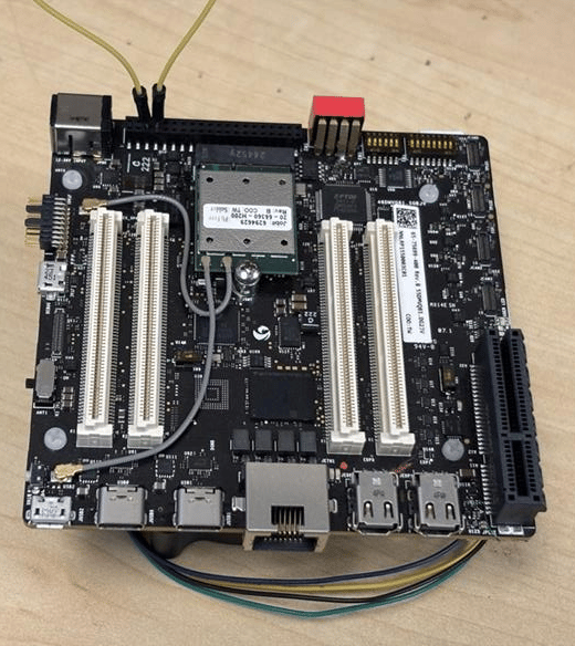 Pay attention to pin order. Do not short power and ground pins — this may damage the board.
```bash theme={null}
stty -F /dev/ttyHS3 ispeed 115200 ospeed 115200
stty -F /dev/ttyHS3 115200 -echo -icanon -isig -iexten -icrnl -ixon -opost
```
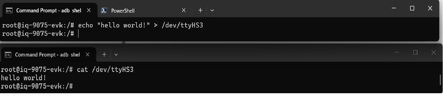
**Terminal 1 (RX):**
```bash theme={null}
cat /dev/ttyHS3
```
**Terminal 2 (TX):**
```bash theme={null}
su
echo "hello world!" > /dev/ttyHS3
```
Pay attention to pin order. Do not short power and ground pins — this may damage the board.
```bash theme={null}
stty -F /dev/ttyHS3 ispeed 115200 ospeed 115200
stty -F /dev/ttyHS3 115200 -echo -icanon -isig -iexten -icrnl -ixon -opost
```
**Terminal 1 (RX):**
```bash theme={null}
cat /dev/ttyHS3
```
**Terminal 2 (TX):**
```bash theme={null}
su
echo "hello world!" > /dev/ttyHS3
```
 ## I2C
I2C (Inter-Integrated Circuit) is a bidirectional 2-wire bus for inter-IC control. Every device on the bus has a unique address. The I2C core supports multi-controller mode, 10-bit target addressing, and 10-bit extendable addressing.
Pins 8 and 10 are configured for I2C by default (GPIO lines 32 and 33, mapping to `i2c4 = qup0_se4 (0x990000)`).
Follow the [Modify serial engine node](./peripheral_interface_overview#modify-serial-engine-node) procedure to enable the I2C interface. After enabling, verify the device nodes:
```bash theme={null}
ls /dev/i2c*
# Expected: /dev/i2c-18 /dev/i2c-19 /dev/i2c-20 /dev/i2c-21 /dev/i2c-22 /dev/i2c-23 /dev/i2c-24 /dev/i2c-25
```
```bash theme={null}
scp i2cdetect root@:/usr
```
```bash theme={null}
i2cdetect -l
```
```bash theme={null}
ls -l /sys/class/i2c-adapter/i2c-*
```
```bash theme={null}
i2cdetect -a -y -r 20
```
```bash theme={null}
# Read all registers of device at address 0x38
i2cdump -f -y 1 0x38
# Write 0xaa to register 0x01
i2cset -f -y 1 0x38 0x01 0xaa
# Read register 0x01
i2cget -f -y 1 0x38 0x01
```
## SPI
SPI (Serial Peripheral Interface) is a synchronous full-duplex 4-wire serial bus.
Pins 11 and 13 are configured for SPI by default (GPIO lines 44 and 45, mapping to `spi10 = qup1_se3 (0xa8c000)`).
Follow the [Modify serial engine node](./peripheral_interface_overview#modify-serial-engine-node) procedure to enable the SPI interface.
## I2C
I2C (Inter-Integrated Circuit) is a bidirectional 2-wire bus for inter-IC control. Every device on the bus has a unique address. The I2C core supports multi-controller mode, 10-bit target addressing, and 10-bit extendable addressing.
Pins 8 and 10 are configured for I2C by default (GPIO lines 32 and 33, mapping to `i2c4 = qup0_se4 (0x990000)`).
Follow the [Modify serial engine node](./peripheral_interface_overview#modify-serial-engine-node) procedure to enable the I2C interface. After enabling, verify the device nodes:
```bash theme={null}
ls /dev/i2c*
# Expected: /dev/i2c-18 /dev/i2c-19 /dev/i2c-20 /dev/i2c-21 /dev/i2c-22 /dev/i2c-23 /dev/i2c-24 /dev/i2c-25
```
```bash theme={null}
scp i2cdetect root@:/usr
```
```bash theme={null}
i2cdetect -l
```
```bash theme={null}
ls -l /sys/class/i2c-adapter/i2c-*
```
```bash theme={null}
i2cdetect -a -y -r 20
```
```bash theme={null}
# Read all registers of device at address 0x38
i2cdump -f -y 1 0x38
# Write 0xaa to register 0x01
i2cset -f -y 1 0x38 0x01 0xaa
# Read register 0x01
i2cget -f -y 1 0x38 0x01
```
## SPI
SPI (Serial Peripheral Interface) is a synchronous full-duplex 4-wire serial bus.
Pins 11 and 13 are configured for SPI by default (GPIO lines 44 and 45, mapping to `spi10 = qup1_se3 (0xa8c000)`).
Follow the [Modify serial engine node](./peripheral_interface_overview#modify-serial-engine-node) procedure to enable the SPI interface.