> ## Documentation Index
> Fetch the complete documentation index at: https://dragonwingdocs.qualcomm.com/llms.txt
> Use this file to discover all available pages before exploring further.
# CAN interface overview
Controller area network (CAN) is a message-based serial communication, which enables quick and reliable sharing of information. The terms CAN and CAN bus are used in the same context. The advantages of CAN are as follows:
* The CAN bus provides one point of entry to communicate with all network nodes enabling central data logging and diagnostics purposes.
* CAN frames are prioritized by message ID. So that the high priority message ID gets control of the bus arbitration. Bitwise arbitration helps manage CAN bus access and avoid collisions through ID-based priority.
* The CAN bus has two logical states during operation:
> * Recessive level, where the recessive bus state is equivalent to logical high and called as the Idle state.
> * Dominant level, where the dominant bus state is equivalent to logical low.
* Any node can transmit data at any time. There is no primary-secondary node concept in case of CAN communication.
* CAN nodes are synchronized using bit-synchronization where each bit time is divided into four segments of time quanta.
* The CAN protocol ensures error handling and detecting CAN errors including CRC and ACK.
## **CAN features**
The CAN protocol supports the following features:
* Priority-based bus access.
* Nondestructive bitwise-based arbitration.
* Broadcast through all-frame transfer.
* Multicast frame transfer by acceptance filtering.
* Error detection and error signaling.
* Automatic deactivation of faulty nodes by identifying the failure nodes.
CAN supports the following data transfer modes. By default, CAN transfer mode is set to the Interrupt mode.
* DMA mode: CAN frames are moved from RX FIFO to system memory through DMA with minimal CPU load.
* Polling mode: CPU periodically checks RX FIFO for new frames and processes them.
* Interrupt mode: When a frame is received, the CPU is notified using an interrupt and it reads the data from the RX FIFO.
The following table lists the CAN channels and the maximum supported baud rates:
| **CAN channel** | **Maximum supported baud rate** |
| :-------------: | :-----------------------------: |
| 0 | 5 MBPS |
| 1 | 12 MBPS |
| 2 | 12 MBPS |
| 3 | 12 MBPS |
| 4 | 12 MBPS |
| 5 | 12 MBPS |
| 6 | 12 MBPS |
| 7 | 12 MBPS |
CAN interface supports the following baud rate range for each channel:
| **Options** | **Nominal bit rate** | **Data bit rate** |
| :---------: | :------------------: | :-------------------------------------: |
| 0 | 500 KBPS | 500 KBPS |
| 1 | 250 KBPS | 5 MBPS |
| 2 | 125 KBPS | 250 KBPS |
| 3 | 1 MBPS | 1 MBPS |
| 4 | 1 MBPS | 2 MBPS |
| 5 | 1 MBPS | 5 MBPS (CAN0 supports till 5 MBPS only) |
| 6 | 1 MBPS | 8 MBPS |
| 7 | 1 MBPS | 10 MBPS |
| 8 | 1 MBPS | 12 MBPS |
## **CAN architecture**
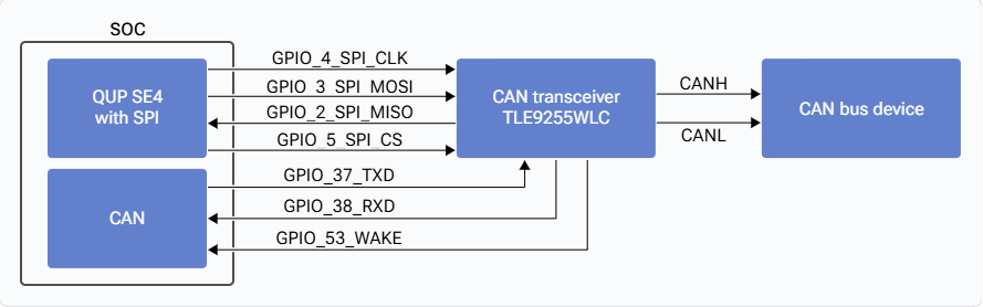
The CAN IP is part of the SoC and it’s a configurable CAN controller. TLE9255WLC is an external transceiver and can be configured through the SPI interface, which works with 4 MHz clock frequency having SPI mode 1. The SoC controller is connected to a QUP block with SE4 configured by a 4-pin SPI operation.
**CAN0**
The Dragonwing IQ-9075 EVK supports eight CAN channels. The Dragonwing IQ-9075 EVK supports the CAN0 connection with the TLE9255WLC transceiver. The following figure shows connection between the CAN0 channels and the TLE9255WLC transceiver that supports the baud rate up to 5 MBPS
 **CAN1/CAN2/CAN3/CAN4/CAN5/CAN6/CAN7**
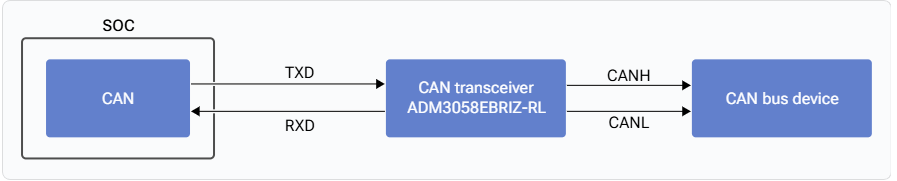
The Dragonwing IQ-9075 EVK supports the CAN1/CAN2/CAN3/CAN4/CAN5/CAN6/CAN7 connection with the ADM3058EBRIZ-RL transceiver. The following figure shows the connection between the CAN1/CAN2/CAN3/CAN4/CAN5/CAN6/CAN7 channels and the ADM3058EBRIZ-RL transceiver that supports the baud rate up to 12 MBPS.
**CAN1/CAN2/CAN3/CAN4/CAN5/CAN6/CAN7**
The Dragonwing IQ-9075 EVK supports the CAN1/CAN2/CAN3/CAN4/CAN5/CAN6/CAN7 connection with the ADM3058EBRIZ-RL transceiver. The following figure shows the connection between the CAN1/CAN2/CAN3/CAN4/CAN5/CAN6/CAN7 channels and the ADM3058EBRIZ-RL transceiver that supports the baud rate up to 12 MBPS.
 **CAN0**
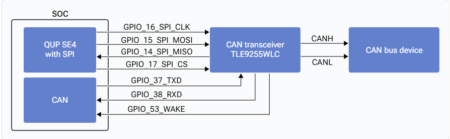
The Dragonwing IQ-8275 EVK supports four CAN channels. The Dragonwing IQ-8275 EVK supports the CAN0 connection with the TLE9255WLC transceiver. The following figure shows connection between the CAN0 channel and the TLE9255WLC transceiver that supports the baud rate up to 5 MBPS:
**CAN0**
The Dragonwing IQ-8275 EVK supports four CAN channels. The Dragonwing IQ-8275 EVK supports the CAN0 connection with the TLE9255WLC transceiver. The following figure shows connection between the CAN0 channel and the TLE9255WLC transceiver that supports the baud rate up to 5 MBPS:
 **CAN1/CAN2/CAN3**
The Dragonwing IQ-8275 EVK supports the CAN1/CAN2/CAN3 connection with the ADM3058EBRIZ-RL transceiver. The following figure shows the connection between the CAN1/CAN2 channels and the ADM3058EBRIZ-RL transceiver that supports the baud rate up to 12 MBPS.
**CAN1/CAN2/CAN3**
The Dragonwing IQ-8275 EVK supports the CAN1/CAN2/CAN3 connection with the ADM3058EBRIZ-RL transceiver. The following figure shows the connection between the CAN1/CAN2 channels and the ADM3058EBRIZ-RL transceiver that supports the baud rate up to 12 MBPS.
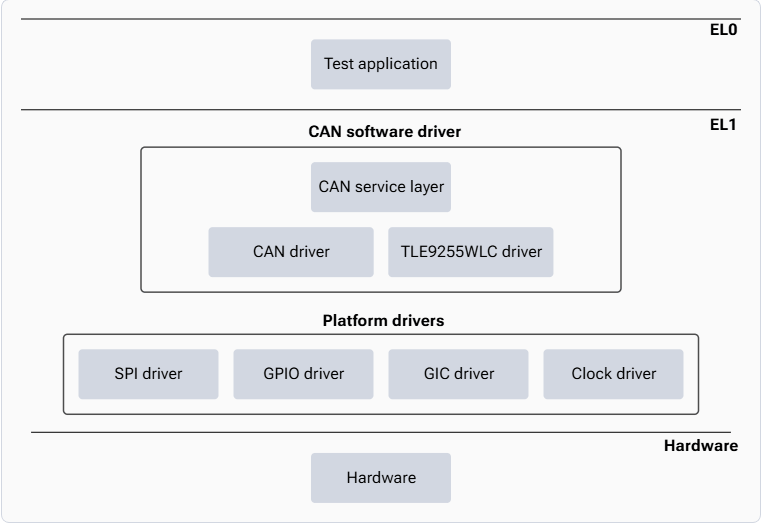
 The user test application communicates with the CAN service layer after registering client callbacks. The CAN service layer acts as an isolation layer between the test application and the CAN and transceiver drivers. The TLE9255WLC transceiver driver is a client of SPI driver to which the QUP\_SPI driver is registered.
 ## **CAN files**
The following are the CAN interface files:
| Test | `sail_proc\BSP\tests\sailsw1\can_test\src\Can_Testapp.c` |
| :--------------------- | :------------------------------------------------------------------------------------------------------------------ |
| API |
## **CAN files**
The following are the CAN interface files:
| Test | `sail_proc\BSP\tests\sailsw1\can_test\src\Can_Testapp.c` |
| :--------------------- | :------------------------------------------------------------------------------------------------------------------ |
| API | - `sail_proc\BSP\can\public\sailel1\CanSrv.h`
- `sail_proc\BSP\can\public\sailel1\Can_Task.h`
|
| SPI to CAN transceiver | `sail_proc\BSP\cantrcv_tle9255\src\sailel1\cantrcv_Task.c` |
| CAN driver | `sail_proc\BSP\can\src\sailel1\Can_Task.c` |
## **Verify CAN interface**
For information about verifying the CAN interface, see [CAN test commands](RTSS-test-commands#can).
## **Customize CAN interface**
Qualcomm recommends using the default CAN transceiver (TLE9255WLC). When the default transceiver is used, software changes aren’t required as the platform CAN software stack provides full support.
If a dummy transceiver (for example, ADM3058EBRIZ) is used, CAN driver changes aren’t required, as all transceiver handling is managed in hardware.
However, if a new or different CAN transceiver is introduced, the corresponding transceiver driver must be integrated and configured in the software. The following sections describe the required changes, using TLE9255 as an example.
**Map transceiver to platform CAN driver**
The new transceiver must be mapped in the platform CAN driver configuration at `sail_proc/BSP/can/src/sailel1/Can_Plt_Cfg.c`.
Example (Dragonwing IQ-8275 EVK):
1. Add a mapping array for the new transceiver:
> ```cpp theme={null}
> CAN_DATA static uint8_t Can_Tle9255_Map[CAN_MTTCAN_MAX_CNT] = {0};
> ```
2. Map the appropriate CAN channel (example for CAN0):
> ```undefined theme={null}
> if (chip_family == CHIPINFO_FAMILY_LEMANSAU)
> {
> Can_Tcan1146_Map[0] = CAN_TCAN_INVALID;
> Can_Tcan1146_Map[1] = CAN_TCAN_INVALID;
> Can_Tcan1146_Map[2] = CAN_TCAN_INVALID;
> Can_Tcan1146_Map[3] = CAN_TCAN_INVALID;
> Can_Tcan1146_Map[4] = CAN_TCAN_INVALID;
> Can_Tcan1146_Map[5] = CAN_TCAN_INVALID;
> Can_Tcan1146_Map[6] = CAN_TCAN_INVALID;
> Can_Tcan1146_Map[7] = CAN_TCAN_INVALID;
>
> Can_Tcan1044_Map[0] = CAN_TCAN_INVALID;
> Can_Tcan1044_Map[1] = CAN_TCAN_INVALID;
> Can_Tcan1044_Map[2] = CAN_TCAN_INVALID;
> Can_Tcan1044_Map[3] = CAN_TCAN_INVALID;
> Can_Tcan1044_Map[4] = CAN_TCAN_INVALID;
> Can_Tcan1044_Map[5] = CAN_TCAN_INVALID;
> Can_Tcan1044_Map[6] = CAN_TCAN_INVALID;
> Can_Tcan1044_Map[7] = CAN_TCAN_INVALID;
>
> Can_Tle9255_Map[0] = CAN_TCAN1146_CHAN_0;
> Can_Tle9255_Map[1] = CAN_TCAN_INVALID;
> Can_Tle9255_Map[2] = CAN_TCAN_INVALID;
> Can_Tle9255_Map[3] = CAN_TCAN_INVALID;
> Can_Tle9255_Map[4] = CAN_TCAN_INVALID;
> Can_Tle9255_Map[5] = CAN_TCAN_INVALID;
> Can_Tle9255_Map[6] = CAN_TCAN_INVALID;
> Can_Tle9255_Map[7] = CAN_TCAN_INVALID;
> }
> ```
**Implement transceiver driver**
A dedicated driver must be implemented for the new transceiver.
Example reference path: `sail_proc/BSP/cantrcv_tle9255/src/sailel1/cantrcv_Task.c`
This driver handles transceiver‑specific operations such as initialization, mode control, and fault handling.
**Initialize transceiver driver**
The new transceiver driver must be initialized during system startup.
File: `sail_proc/BSP/el_entry/src/sailsw1/sailel1_main.c`
Add the initialization call for the new transceiver driver.
Example:
```undefined theme={null}
CanTrcv_Tle9255_Init();
```