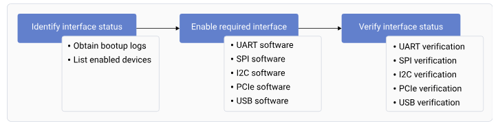
***Figure : Interface workflow***
## **Identify the interface status** The default interface status indicates the status of the interfaces during bootup. To identify the interface status, successfully register the interfaces and obtain the list of enabled interfaces. ### **Obtain the bootup logs** To obtain the bootup logs of the device, do the following: 1. Open the SSH shell in permissive mode or use the ADB shell. For more information about how to run SSH, see the [Use SSH](https://docs.qualcomm.com/doc/80-80021-254/topic/how_to.html) section. 2. Obtain the logs of the enabled interfaces by running the following command. ```text theme={null} dmesg ``` Output: ```text theme={null} [ 0.434365] msm_serial: driver initialized [ 0.799123] 994000.serial: ttyMSM0 at MMIO 0x994000 (irq = 139, base_baud = 0) is a MSM [ 0.801937] 99c000.serial: ttyHS1 at MMIO 0x99c000 (irq = 140, base_baud = 0) is a MSM [ 0.804563] serial serial0: tty port ttyHS1 registered [ 0.720945] usbhub_rest_vreg GPIO handle specifies active low - ignored [ 0.815241] dwc3-qcom 8c00000.usb: Adding to iommu group 4 [ 5.195974] dwc3-qcom a600000.usb: Adding to iommu group 18 [ 5.229464] qcom_pmic_glink pmic-glink: Failed to create device link (0x180) with a600000.usb [ 6.195825] usb usb2: We don't know the algorithms for LPM for this host, disabling LPM. [ 6.450338] usb 1-1: new high-speed USB device number 2 using xhci_hcd [ 6.664583] usbcore: registered new device driver onboard-usb-hub [ 6.730998] usb 2-1: new SuperSpeed USB device number 2 using xhci_hcd [ 7.083668] usb 2-1.1: new SuperSpeed USB device number 3 using xhci_hcd [ 7.217287] ax88179_178a 2-1.1:1.0 eth0: register 'ax88179_178a' at usb-0001:04:00.0-1.1, ASIX AX88179 USB 3.0 Gigabit Ethernet, 02:fe:ee:05:44:23 [ 7.217415] usbcore: registered new interface driver ax88179_178a [ 10.223140] dwc3-qcom a600000.usb: request 0000000000000000 was not queued to ep0ou ``` 3. Connect the UART serial port to log in to the console.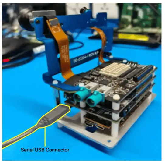 ### **List enabled interfaces on devices**
To obtain the list of the enabled interfaces, do the following:
* For UART, run the following command.
```text theme={null}
ls /dev/tty*
```
Output:
```text theme={null}
/dev/tty /dev/tty21 /dev/tty35 /dev/tty49 /dev/tty62 /dev/ttyp4
/dev/tty0 /dev/tty22 /dev/tty36 /dev/tty5 /dev/tty63 /dev/ttyp5
/dev/tty1 /dev/tty23 /dev/tty37 /dev/tty50 /dev/tty7 /dev/ttyp6
/dev/tty10 /dev/tty24 /dev/tty38 /dev/tty51 /dev/tty8 /dev/ttyp7
/dev/tty11 /dev/tty25 /dev/tty39 /dev/tty52 /dev/tty9 /dev/ttyp8
/dev/tty12 /dev/tty26 /dev/tty4 /dev/tty53 /dev/ttyMSM0 /dev/ttyp9
/dev/tty13 /dev/tty27 /dev/tty40 /dev/tty54 /dev/ttyS0 /dev/ttypa
/dev/tty14 /dev/tty28 /dev/tty41 /dev/tty55 /dev/ttyS1 /dev/ttypb
/dev/tty15 /dev/tty29 /dev/tty42 /dev/tty56 /dev/ttyS2 /dev/ttypc
/dev/tty16 /dev/tty3 /dev/tty43 /dev/tty57 /dev/ttyS3 /dev/ttypd
/dev/tty17 /dev/tty30 /dev/tty44 /dev/tty58 /dev/ttynull /dev/ttype
/dev/tty18 /dev/tty31 /dev/tty45 /dev/tty59 /dev/ttyp0 /dev/ttypf
/dev/tty19 /dev/tty32 /dev/tty46 /dev/tty6 /dev/ttyp1
/dev/tty2 /dev/tty33 /dev/tty47 /dev/tty60 /dev/ttyp2
/dev/tty20 /dev/tty34 /dev/tty48 /dev/tty61 /dev/ttyp3
```
* For I2C, run the following command.
```text theme={null}
ls /dev/i2c*
```
The following output is displayed.
```text theme={null}
/dev/i2c-0 /dev/i2c-1 /dev/i2c-16
```
* By default, SPI isn't enabled. To enable SPI, see [SPI software device tree configuration](https://dragonwingdocs.qualcomm.com/System/Interfaces/spi#spi-software-device-tree-configuration). To verify if SPI is enabled, run the following command.
```text theme={null}
ls /dev/spi*
```
The following output is displayed.
```text theme={null}
spidev14.0
```
* For PCIe, obtain the enumeration log. For more information about PCIe probe logs, see [PCIe-related configurations](https://dragonwingdocs.qualcomm.com/System/Interfaces/pcie#pcie-related-configurations) and [QPS615 switch support](https://docs.qualcomm.com/doc/80-80021-8/topic/pcie.html?product=895724676033554725\&facet=Interfaces\&version=2.0-rc2#pcie-software-support-feature-for-qps615__section_nmw_5jd_l1c).
## **Load QUP v3 serial engine firmware using Linux kernel**
This document explains the QUP v3 serial engine firmware loading mechanism using the Linux kernel. It describes the transition from a TrustZone-based architecture—which had fixed protocol assignments and limited flexibility—to a Linux-based approach that enables dynamic protocol assignment, easier debugging, and simplified development through device tree configuration. QUP v3 contains multiple serial engines that can be configured as follows:
* I2C
* SPI
* UART
### **Default configuration**
The default configuration for each serial engine, including the selected mode of data transmission and ownership, is in the `_/TZ.XF.5.0/core.tz/2.0/settings/buses/qup\_accesscontrol/qupv3/config/lemans/QUPAC\_Access.c_` file.
In the default configuration, Linux owns all the serial engines.
```text theme={null}
const QUPv3_se_security_permissions_type qupv3_perms_default =
{
/* PeriphID, ProtocolID, Mode, NsOwner, bAllowFifo, bLoad, bModExcl */
/*QUPV3_0_SE0*/
/*QUPV3_0_SE1*/
/*QUPV3_0_SE2*/
{ QUPV3_0_SE3, QUPV3_PROTOCOL_UART_4W, QUPV3_MODE_FIFO, AC_HLOS, TRUE, TRUE, FALSE }, // BT UART (2nd Hastings)
{ QUPV3_0_SE4, QUPV3_PROTOCOL_UART_2W, QUPV3_MODE_FIFO, AC_HLOS, TRUE, TRUE, FALSE }, // VIP UART/SPI (SOC SLAVE)
/*QUPV3_0_SE5*/ // Spare
{ QUPV3_1_SE0, QUPV3_PROTOCOL_I2C, QUPV3_MODE_FIFO, AC_HLOS, TRUE, TRUE, FALSE }, // I2C Carplay
/*QUPV3_1_SE1*/
{ QUPV3_1_SE2, QUPV3_PROTOCOL_UART_2W, QUPV3_MODE_FIFO, AC_HLOS, TRUE, TRUE, FALSE }, // Tuner
{ QUPV3_1_SE3, QUPV3_PROTOCOL_UART_2W, QUPV3_MODE_FIFO, AC_HLOS, TRUE, FALSE, FALSE }, // Debug UART
{ QUPV3_1_SE4, QUPV3_PROTOCOL_I2C, QUPV3_MODE_FIFO, AC_HLOS, TRUE, TRUE, FALSE }, // I2C A2B Controller & Audio port expander
{ QUPV3_1_SE5, QUPV3_PROTOCOL_UART_2W, QUPV3_MODE_FIFO, AC_HLOS, TRUE, TRUE, FALSE }, // GNSS
/*QUPV3_1_SE6*/
{ QUPV3_2_SE0, QUPV3_PROTOCOL_SPI, QUPV3_MODE_FIFO, AC_HLOS, TRUE, TRUE, FALSE }, // FPGA
{ QUPV3_2_SE1, QUPV3_PROTOCOL_I2C, QUPV3_MODE_FIFO, AC_HLOS, TRUE, TRUE, FALSE }, // PCIe I2C MUX
{ QUPV3_2_SE2, QUPV3_PROTOCOL_SPI, QUPV3_MODE_FIFO, AC_HLOS, TRUE, TRUE, FALSE }, // SPI - Audio
{ QUPV3_2_SE3, QUPV3_PROTOCOL_UART_4W, QUPV3_MODE_FIFO, AC_HLOS, TRUE, TRUE, FALSE }, // BT UART
{ QUPV3_2_SE4, QUPV3_PROTOCOL_I2C, QUPV3_MODE_FIFO, AC_HLOS, TRUE, TRUE, FALSE }, // I2C Display 1
{ QUPV3_2_SE5, QUPV3_PROTOCOL_I2C, QUPV3_MODE_FIFO, AC_HLOS, TRUE, TRUE, FALSE }, // I2C Sensor
/*QUPV3_2_SE6 */
{ QUPV3_3_SE0, QUPV3_PROTOCOL_SPI, QUPV3_MODE_FIFO, AC_HLOS, TRUE, FALSE, FALSE }, // SPI
};
```
### **Load firmware**
The firmware files are at */lib/firmware/qcom/\
### **List enabled interfaces on devices**
To obtain the list of the enabled interfaces, do the following:
* For UART, run the following command.
```text theme={null}
ls /dev/tty*
```
Output:
```text theme={null}
/dev/tty /dev/tty21 /dev/tty35 /dev/tty49 /dev/tty62 /dev/ttyp4
/dev/tty0 /dev/tty22 /dev/tty36 /dev/tty5 /dev/tty63 /dev/ttyp5
/dev/tty1 /dev/tty23 /dev/tty37 /dev/tty50 /dev/tty7 /dev/ttyp6
/dev/tty10 /dev/tty24 /dev/tty38 /dev/tty51 /dev/tty8 /dev/ttyp7
/dev/tty11 /dev/tty25 /dev/tty39 /dev/tty52 /dev/tty9 /dev/ttyp8
/dev/tty12 /dev/tty26 /dev/tty4 /dev/tty53 /dev/ttyMSM0 /dev/ttyp9
/dev/tty13 /dev/tty27 /dev/tty40 /dev/tty54 /dev/ttyS0 /dev/ttypa
/dev/tty14 /dev/tty28 /dev/tty41 /dev/tty55 /dev/ttyS1 /dev/ttypb
/dev/tty15 /dev/tty29 /dev/tty42 /dev/tty56 /dev/ttyS2 /dev/ttypc
/dev/tty16 /dev/tty3 /dev/tty43 /dev/tty57 /dev/ttyS3 /dev/ttypd
/dev/tty17 /dev/tty30 /dev/tty44 /dev/tty58 /dev/ttynull /dev/ttype
/dev/tty18 /dev/tty31 /dev/tty45 /dev/tty59 /dev/ttyp0 /dev/ttypf
/dev/tty19 /dev/tty32 /dev/tty46 /dev/tty6 /dev/ttyp1
/dev/tty2 /dev/tty33 /dev/tty47 /dev/tty60 /dev/ttyp2
/dev/tty20 /dev/tty34 /dev/tty48 /dev/tty61 /dev/ttyp3
```
* For I2C, run the following command.
```text theme={null}
ls /dev/i2c*
```
The following output is displayed.
```text theme={null}
/dev/i2c-0 /dev/i2c-1 /dev/i2c-16
```
* By default, SPI isn't enabled. To enable SPI, see [SPI software device tree configuration](https://dragonwingdocs.qualcomm.com/System/Interfaces/spi#spi-software-device-tree-configuration). To verify if SPI is enabled, run the following command.
```text theme={null}
ls /dev/spi*
```
The following output is displayed.
```text theme={null}
spidev14.0
```
* For PCIe, obtain the enumeration log. For more information about PCIe probe logs, see [PCIe-related configurations](https://dragonwingdocs.qualcomm.com/System/Interfaces/pcie#pcie-related-configurations) and [QPS615 switch support](https://docs.qualcomm.com/doc/80-80021-8/topic/pcie.html?product=895724676033554725\&facet=Interfaces\&version=2.0-rc2#pcie-software-support-feature-for-qps615__section_nmw_5jd_l1c).
## **Load QUP v3 serial engine firmware using Linux kernel**
This document explains the QUP v3 serial engine firmware loading mechanism using the Linux kernel. It describes the transition from a TrustZone-based architecture—which had fixed protocol assignments and limited flexibility—to a Linux-based approach that enables dynamic protocol assignment, easier debugging, and simplified development through device tree configuration. QUP v3 contains multiple serial engines that can be configured as follows:
* I2C
* SPI
* UART
### **Default configuration**
The default configuration for each serial engine, including the selected mode of data transmission and ownership, is in the `_/TZ.XF.5.0/core.tz/2.0/settings/buses/qup\_accesscontrol/qupv3/config/lemans/QUPAC\_Access.c_` file.
In the default configuration, Linux owns all the serial engines.
```text theme={null}
const QUPv3_se_security_permissions_type qupv3_perms_default =
{
/* PeriphID, ProtocolID, Mode, NsOwner, bAllowFifo, bLoad, bModExcl */
/*QUPV3_0_SE0*/
/*QUPV3_0_SE1*/
/*QUPV3_0_SE2*/
{ QUPV3_0_SE3, QUPV3_PROTOCOL_UART_4W, QUPV3_MODE_FIFO, AC_HLOS, TRUE, TRUE, FALSE }, // BT UART (2nd Hastings)
{ QUPV3_0_SE4, QUPV3_PROTOCOL_UART_2W, QUPV3_MODE_FIFO, AC_HLOS, TRUE, TRUE, FALSE }, // VIP UART/SPI (SOC SLAVE)
/*QUPV3_0_SE5*/ // Spare
{ QUPV3_1_SE0, QUPV3_PROTOCOL_I2C, QUPV3_MODE_FIFO, AC_HLOS, TRUE, TRUE, FALSE }, // I2C Carplay
/*QUPV3_1_SE1*/
{ QUPV3_1_SE2, QUPV3_PROTOCOL_UART_2W, QUPV3_MODE_FIFO, AC_HLOS, TRUE, TRUE, FALSE }, // Tuner
{ QUPV3_1_SE3, QUPV3_PROTOCOL_UART_2W, QUPV3_MODE_FIFO, AC_HLOS, TRUE, FALSE, FALSE }, // Debug UART
{ QUPV3_1_SE4, QUPV3_PROTOCOL_I2C, QUPV3_MODE_FIFO, AC_HLOS, TRUE, TRUE, FALSE }, // I2C A2B Controller & Audio port expander
{ QUPV3_1_SE5, QUPV3_PROTOCOL_UART_2W, QUPV3_MODE_FIFO, AC_HLOS, TRUE, TRUE, FALSE }, // GNSS
/*QUPV3_1_SE6*/
{ QUPV3_2_SE0, QUPV3_PROTOCOL_SPI, QUPV3_MODE_FIFO, AC_HLOS, TRUE, TRUE, FALSE }, // FPGA
{ QUPV3_2_SE1, QUPV3_PROTOCOL_I2C, QUPV3_MODE_FIFO, AC_HLOS, TRUE, TRUE, FALSE }, // PCIe I2C MUX
{ QUPV3_2_SE2, QUPV3_PROTOCOL_SPI, QUPV3_MODE_FIFO, AC_HLOS, TRUE, TRUE, FALSE }, // SPI - Audio
{ QUPV3_2_SE3, QUPV3_PROTOCOL_UART_4W, QUPV3_MODE_FIFO, AC_HLOS, TRUE, TRUE, FALSE }, // BT UART
{ QUPV3_2_SE4, QUPV3_PROTOCOL_I2C, QUPV3_MODE_FIFO, AC_HLOS, TRUE, TRUE, FALSE }, // I2C Display 1
{ QUPV3_2_SE5, QUPV3_PROTOCOL_I2C, QUPV3_MODE_FIFO, AC_HLOS, TRUE, TRUE, FALSE }, // I2C Sensor
/*QUPV3_2_SE6 */
{ QUPV3_3_SE0, QUPV3_PROTOCOL_SPI, QUPV3_MODE_FIFO, AC_HLOS, TRUE, FALSE, FALSE }, // SPI
};
```
### **Load firmware**
The firmware files are at */lib/firmware/qcom/\| Property | Type | Description | Required |
|---|---|---|---|
| `status` | string | Enable/disable SE (`okay`/`disabled`) | Yes |
| `qcom,enable-gsi-dma` | boolean | Enable GSI DMA mode | No |
| `clock-frequency` | u32 | I2C clock frequency (Hz) | No |
| `spi-max-frequency` | u32 | SPI max frequency (Hz) | No |
| `pinctrl-names` | string array | Pin control state names | Recommended |
| `pinctrl-0` | phandle | Default pin configuration | Recommended |
| Attribute | FIFO mode | GSI DMA mode |
|---|---|---|
| Data path | Uses internal FIFO buffers | Uses GSI DMA mode |
| Best for | Small, frequent transfers; simple device communication | Large or bulk transfers; high-throughput devices (touchscreen, display) |
| Overhead | Lower overhead | Higher setup overhead, but offloads CPU for large transfers |
| Configuration | Default mode; no special configuration needed | Requires `qcom,enable-gsi-dma;` property in device tree |
| DMA channel use | Not required | Requires available DMA channels; limited by platform |
| Performance | Lower throughput for large data; low latency | Higher throughput for large data; CPU efficient |
| When to use | When DMA channels are limited, or for low-latency/small transfers | For transfer size > 32 bytes, or for bulk/high-speed data |
| Limitations | Not optimal for large or high-speed transfers | Limited by number of DMA channels; not all SEs may support GSI DMA |
| Device tree example | Omit `qcom,enable-gsi-dma;` property | Add `qcom,enable-gsi-dma;` property |
| Debugging | Standard Linux debugging tools; kernel logs | Similar to FIFO, but also includes DMA allocation logs |
| Mode | When to use |
|---|---|
| GSI DMA mode (`qcom,enable-gsi-dma;`) | Transfer sizes > 32 bytes regularly, High-throughput devices (touchscreens, displays), Bulk data transfers, CPU efficiency is critical |
| FIFO mode | Small, frequent transfers, Low-latency requirements, Limited DMA channels available, Simple device communication |
| Issue | Symptoms | Solutions |
|---|---|---|
| Firmware Loading Failed | `qcom-geni-se`: firmware request failed |
|
| Serial engine not probing |
|
|
| Protocol conflict | `qcom-geni-se`: serial engine is already in use | Ensure only one protocol enabled per serial engine. |
| DMA allocation failed | `qcom-geni-se`: GSI DMA allocation failed |
|
| Pin Mux conflict |
|
|