> ## Documentation Index
> Fetch the complete documentation index at: https://dragonwingdocs.qualcomm.com/llms.txt
> Use this file to discover all available pages before exploring further.
# I2C
export const tdA = {
border: "1px solid #ddd",
padding: "10px 14px",
textAlign: "left",
verticalAlign: "top"
};
export const thA1 = {
border: "1px solid #ddd",
padding: "10px 14px",
textAlign: "center",
backgroundColor: "#f5f5f5",
fontWeight: "600",
color: "#333",
width: "20%"
};
export const thA2 = {
border: "1px solid #ddd",
padding: "10px 14px",
textAlign: "center",
backgroundColor: "#f5f5f5",
fontWeight: "600",
color: "#333",
width: "80%"
};
export const thAeq = {
border: "1px solid #ddd",
padding: "10px 14px",
textAlign: "center",
backgroundColor: "#f5f5f5",
fontWeight: "600",
color: "#333"
};
export const tblA = {
borderCollapse: "collapse",
width: "100%",
fontSize: "14px",
tableLayout: "fixed"
};
Interintegrated circuit (I2C) is a bidirectional 2-wire bus for an efficient inter‑IC control bus developed by Philips in the 1980s. Every device on the bus has its own unique address (registered with the I2C general body headed by Philips). The I2C core supports a multicontroller mode and 10‑bit target address and 10‑bit extendable address. For more information about I2C, see [https://www.i2c-bus.org/fileadmin/ftp/i2c\_bus\_specification\_1995.pdf](https://www.i2c-bus.org/fileadmin/ftp/i2c_bus_specification_1995.pdf).
### **I2C communication sequence overview**
The following figure shows the communication sequence between the controller and targets in I2C.
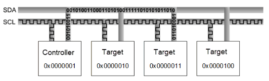
Figure : I2C controller and target communication sequence
For example, no device can use 1111-0XX listed in the I2C specification and high-speed mode with 3.4 MHz clock frequency.
Following are the I2C modes and supported speeds.
* Standard mode: 100 kbps
* Fast mode: 400 kbps
* Fast mode plus: 1 Mbps
The maximum supported bandwidth is 1 MHz.
### **I2C data packet format**
The controller sends a 7‑bit or 10‑bit address as shown in the following figure. Along with the address, a 1‑bit read/write indicating the type of operation is also sent. Data is transferred in sequences of 8 bits placed on an SDA line. For every byte transferred, the device receiving the data sends back an ACK bit (totaling nine clock pulses).
* ACK bit LOW: receives the data and is ready to accept the next byte.
* ACK bit HIGH: receives the data and can't accept further data. The controller then terminates the transmission with the STOP sequence.
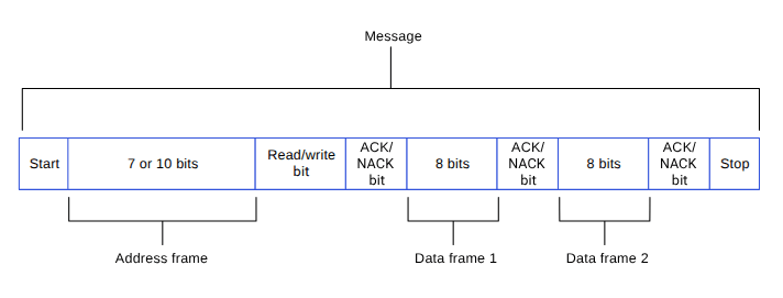
Figure : I2C data packet
### **I2C sequences**
When the SCL is high, the SDA must remain stable and can't change. Only when the clock line is low can the data line change. However, there are two exceptions: START and STOP sequences.
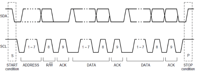
Figure : I2C sequence
## **I2C features**
This section explains the I2C serial engine transfer modes and the different scenarios where each mode is used. The following table lists the transfer modes enabled in the various I2C subsystem drivers.
**Table : I2C transfer modes**
| Subsystem |
Transfer mode |
Description |
| Linux |
- FIFO (low speed)
- CPU DMA (high speed)
- GSI
|
- Supports 100 kHz, 400 kHz, and 1000 kHz bus speeds
- Supports 7‑bit target address according to the I2C specification
|
| Boot |
FIFO |
|
| aDSP/Qualcomm TEE/SDC |
FIFO |
|
## **I2C interface components**
This section provides information about the subsystem driver, kernel device tree nodes, and related documentation.
**Table : I2C interface: Linux**
| File type |
Description |
| Device tree source |
- QCS6490 and QCS5430: [https://git.linaro.org/kernel-org/linux-next.git/tree/arch/arm64/boot/dts/qcom/sc7280.dtsi](https://git.linaro.org/kernel-org/linux-next.git/tree/arch/arm64/boot/dts/qcom/sc7280.dtsi)
- Dragonwing IQ-9075: [https://github.com/torvalds/linux/blob/master/arch/arm64/boot/dts/qcom/sa8775p.dtsi](https://github.com/torvalds/linux/blob/master/arch/arm64/boot/dts/qcom/sa8775p.dtsi)
- Dragonwing IQ-615: [https://git.kernel.org/pub/scm/linux/kernel/git/qcom/linux.git/tree/arch/arm64/boot/dts/qcom/qcs615.dtsi?h=arm64-for-6.16](https://git.kernel.org/pub/scm/linux/kernel/git/qcom/linux.git/tree/arch/arm64/boot/dts/qcom/qcs615.dtsi?h=arm64-for-6.16)
|
| `Pinctrl` settings |
- QCS6490 and QCS5430: [https://git.linaro.org/kernel-org/linux-next.git/tree/arch/arm64/boot/dts/qcom/sc7280.dtsi](https://git.linaro.org/kernel-org/linux-next.git/tree/arch/arm64/boot/dts/qcom/sc7280.dtsi)
- Dragonwing IQ-9075: [https://github.com/torvalds/linux/blob/master/arch/arm64/boot/dts/qcom/sa8775p.dtsi](https://github.com/torvalds/linux/blob/master/arch/arm64/boot/dts/qcom/sa8775p.dtsi)
- Dragonwing IQ-615: [https://git.kernel.org/pub/scm/linux/kernel/git/qcom/linux.git/tree/arch/arm64/boot/dts/qcom/qcs615.dtsi?h=arm64-for-6.16](https://git.kernel.org/pub/scm/linux/kernel/git/qcom/linux.git/tree/arch/arm64/boot/dts/qcom/qcs615.dtsi?h=arm64-for-6.16)
|
| Qualcomm TEE settings |
- `/firmware/qualcomm-linux-spf-1-0_ap_standard_oem_nomodem/TZ.XF.5.0/trustzone_images/core/settings/buses/qup_accesscontrol/qupv3/config//QUPAC_Access.c`
|
**Table : I2C interface: Boot**
| File type |
Description |
| QUP v3 serial engine configuration |
- QUP v3 serial engine: `/firmware/qualcomm-linux-spf-1-0_ap_standard_oem_nomodem/BOOT.MXF.1.0.c1/boot_images/boot/Settings/Soc//Core/Buses/qup_common/-qupv3.dtsi`
- GPIO configurations: `/firmware/qualcomm-linux-spf-1-0_ap_standard_oem_nomodem/BOOT.MXF.1.0.c1/boot_images/boot/Settings/Soc//Core/Buses/qup_common/-qupv3-pinctrl.dtsi`
|
| Qualcomm TEE settings |
- `/firmware/qualcomm-linux-spf-1-0_ap_standard_oem_nomodem/TZ.XF.5.0/trustzone_images/core/settings/buses/qup_accesscontrol/qupv3/config//QUPAC_Access.c`
|
**Table : I2C interface: aDSP/SLPI/SDC**
| File type |
Description |
| QUP v3 serial engine configuration |
- `/firmware/qualcomm-linux-spf-1-0_ap_standard_oem_nomodem/ADSP.HT.5.5.c8/adsp_proc/core/settings/buses/qup_common/config//adsp/ssc/qup_devcfg.c`
- `/firmware/qualcomm-linux-spf-1-0_ap_standard_oem_nomodem/ADSP.HT.5.5.c8/adsp_proc/core/settings/buses/qup_fw/config//fw_devcfg.c`
- `settings/buses/qup_common/config//adsp/ssc/qup_devcfg.json`
|
| Firmware configuration settings |
- `/firmware/qualcomm-linux-spf-1-0_ap_standard_oem_nomodem/ADSP.HT.5.5.c8/adsp_proc/core/settings/buses/qup_fw/config//fw_devcfg.c`
- `/firmware/qualcomm-linux-spf-1-0_ap_standard_oem_nomodem/ADSP.HT.5.5.c8/adsp_proc/core/settings/buses/qup_fw/config//fw_devcfg.xml`
|
**Table : I2C interface: Qualcomm TEE**
| File type |
Description |
| QUP v3 serial engine configuration |
- `/firmware/qualcomm-linux-spf-1-0_ap_standard_oem_nomodem/TZ.XF.5.0/trustzone_images/core/settings/buses/i2c/qupv3/config//tz/i2c_devcfg_user.h`
- `/firmware/qualcomm-linux-spf-1-0_ap_standard_oem_nomodem/TZ.XF.5.0/trustzone_images/core/settings/buses/i2c/qupv3/config//tz/i2c_devcfg_user.c`
- `/firmware/qualcomm-linux-spf-1-0_ap_standard_oem_nomodem/TZ.XF.5.0/trustzone_images/core/settings/buses/i2c/qupv3/config//tz/i2c_devcfg.xml`
|
| Qualcomm TEE settings |
- `/firmware/qualcomm-linux-spf-1-0_ap_standard_oem_nomodem/TZ.XF.5.0/trustzone_images/core/settings/buses/qup_accesscontrol/qupv3/config//QUPAC_Access.c`
|
### **I2C APIs**
I2C APIs for the following subsystems are listed in this section.
* Linux:
* [https://github.com/torvalds/linux/blob/master/include/linux/i2c.h](https://github.com/torvalds/linux/blob/master/include/linux/i2c.h).
* [https://github.com/torvalds/linux/blob/master/include/linux/i2c-dev.h](https://github.com/torvalds/linux/blob/master/include/linux/i2c-dev.h).
* Boot: boot\_images/boot/QcomPkg/Include/i2c\_api.h
* aDSP/SDC/SLPI: adsp\_proc/core/api/buses/i2c\_api.h
* Qualcomm TEE: trustzone\_images/core/buses/api/i2c/qupv3/i2c\_api.h
## **I2C software device tree configuration**
This section provides information on the I2C device tree configuration, and documentation for the device nodes.
### **Linux**
For the configuration settings file, see the following DTSI files.
* QCS6490 and QCS5430: [https://git.linaro.org/kernel-org/linux-next.git/tree/arch/arm64/boot/dts/qcom/sc7280.dtsi](https://git.linaro.org/kernel-org/linux-next.git/tree/arch/arm64/boot/dts/qcom/sc7280.dtsi)
* Dragonwing IQ-9075: [https://github.com/torvalds/linux/blob/master/arch/arm64/boot/dts/qcom/sa8775p.dtsi](https://github.com/torvalds/linux/blob/master/arch/arm64/boot/dts/qcom/sa8775p.dtsi)
* Dragonwing IQ-615: [https://git.kernel.org/pub/scm/linux/kernel/git/qcom/linux.git/tree/arch/arm64/boot/dts/qcom/qcs615.dtsi?h=arm64-for-6.16](https://git.kernel.org/pub/scm/linux/kernel/git/qcom/linux.git/tree/arch/arm64/boot/dts/qcom/qcs615.dtsi?h=arm64-for-6.16)
For more details, see the `i2c-geni-qcom.yaml` file at [https://github.com/torvalds/linux/blob/master/Documentation/devicetree/bindings/i2c/qcom%2Ci2c-geni-qcom.yaml](https://github.com/torvalds/linux/blob/master/Documentation/devicetree/bindings/i2c/qcom%2Ci2c-geni-qcom.yaml), and the I2C driver at the [https://github.com/torvalds/linux/blob/master/drivers/i2c/busses/i2c-qcom-geni.c](https://github.com/torvalds/linux/blob/master/drivers/i2c/busses/i2c-qcom-geni.c) files.
```text theme={null}
i2c1: i2c@984000 {
compatible = "qcom,geni-i2c";
reg = <0 0x00984000 0 0x4000>;
clocks = <&gcc GCC_QUPV3_WRAP0_S1_CLK>;
clock-names = "se";
pinctrl-names = "default";
pinctrl-0 = <&qup_i2c1_data_clk>;
interrupts = ;
#address-cells = <1>;
#size-cells = <0>;
interconnects = <&clk_virt MASTER_QUP_CORE_0 0 &clk_virt SLAVE_QUP_CORE_0 0>,
<&gem_noc MASTER_APPSS_PROC 0 &cnoc2 SLAVE_QUP_0 0>,
<&aggre1_noc MASTER_QUP_0 0 &mc_virt SLAVE_EBI1 0>;
interconnect-names = "qup-core", "qup-config",
"qup-memory";
power-domains = <&rpmhpd SC7280_CX>;
required-opps = <&rpmhpd_opp_low_svs>;
dmas = <&gpi_dma0 0 1 QCOM_GPI_I2C>,
<&gpi_dma0 1 1 QCOM_GPI_I2C>;
dma-names = "tx", "rx";
status = "disabled";
};
```
For kernel documentation specific to the GPIO `pinctrl` configuration, see the following files.
* QCS6490 and QCS5430: [https://git.linaro.org/kernel-org/linux-next.git/tree/arch/arm64/boot/dts/qcom/sc7280.dtsi](https://git.linaro.org/kernel-org/linux-next.git/tree/arch/arm64/boot/dts/qcom/sc7280.dtsi)
* Dragonwing IQ-9075: [https://github.com/torvalds/linux/blob/master/arch/arm64/boot/dts/qcom/sa8775p.dtsi](https://github.com/torvalds/linux/blob/master/arch/arm64/boot/dts/qcom/sa8775p.dtsi)
* Dragonwing IQ-615: [https://git.kernel.org/pub/scm/linux/kernel/git/qcom/linux.git/tree/arch/arm64/boot/dts/qcom/qcs615.dtsi?h=arm64-for-6.16](https://git.kernel.org/pub/scm/linux/kernel/git/qcom/linux.git/tree/arch/arm64/boot/dts/qcom/qcs615.dtsi?h=arm64-for-6.16)
* `Documentation/devicetree/bindings/pinctrl/qcom,-tlmm.yaml`
The corresponding configurations of the QUP v3 serial engine GPIOs are present and mapped in the `pinctrl.dtsi` file.
```text theme={null}
qup_i2c1_data_clk: qup-i2c1-data-clk-state {
pins = "gpio4", "gpio5";
function = "qup01";
};
```
In the `QUPAC_Access.c` file, ensure that the particular serial engine configuration for the specified protocol is for the I2C protocol. Qualcomm TEE build:
```text theme={null}
/firmware/qualcomm-linux-spf-1-0_ap_standard_oem_nomodem/TZ.XF.5.0/trustzone_images/core/settings/buses/qup_accesscontrol/qupv3/config//QUPAC_Access.c
```
Modify the required settings or refer to the default settings assigned for the QUP v3 serial engine instances. The following sample configuration is enabled by default in I2C.
```text theme={null}
/* PeriphID, ProtocolID, Mode, NsOwner, bAllowFifo, bLoad, bModExcl */
{ QUPV3_0_SE0, QUPV3_PROTOCOL_I2C, QUPV3_MODE_FIFO, AC_HLOS, TRUE, TRUE, FALSE }, // LT9611 and QPS615 I2C
{ QUPV3_0_SE1, QUPV3_PROTOCOL_I2C, QUPV3_MODE_FIFO, AC_HLOS, TRUE, TRUE, FALSE }, // APPS I2C - PCIE/ USB Type C
{ QUPV3_0_SE2, QUPV3_PROTOCOL_I2C, QUPV3_MODE_FIFO, AC_HLOS, TRUE, TRUE, FALSE }, // SMB / LS1 I2C
{ QUPV3_1_SE1, QUPV3_PROTOCOL_I2C, QUPV3_MODE_FIFO, AC_HLOS, TRUE, TRUE, FALSE }, // NFC I2C
{ QUPV3_1_SE2, QUPV3_PROTOCOL_I2C, QUPV3_MODE_FIFO, AC_HLOS, TRUE, TRUE, FALSE }, // HDMI OUT for
{ QUPV3_1_SE5, QUPV3_PROTOCOL_I2C, QUPV3_MODE_GSI, AC_HLOS, FALSE, TRUE, FALSE}, // Legacy Touch
```
### **Boot**
1. Configure I2C in the UEFI. The configuration files can be accessed from the following locations.
* QUP v3 serial engine: `/firmware/qualcomm-linux-spf-1-0_ap_standard_oem_nomodem/BOOT.MXF.1.0.c1/boot_images/boot/Settings/Soc//Core/Buses/qup_common/-qupv3.dtsi`
* Qualcomm TEE settings: `/firmware/qualcomm-linux-spf-1-0_ap_standard_oem_nomodem/TZ.XF.5.0/trustzone_images/core/settings/buses/qup_accesscontrol/qupv3/config//QUPAC_Access.c`
Note: For configuration settings in boot, see [Boot](https://dragonwingdocs.qualcomm.com/System/Interfaces/spi#boot).
2. Enable the I2C protocol in UEFI at `/QcomPkg/SocPkg//LAA/Core.fdf`.
```text theme={null}
-#INF QcomPkg/Drivers/I2CDxe/I2CDxe.inf
+INF QcomPkg/Drivers/I2CDxe/I2CDxe.inf
```
3. The application enables the I2C interface. The application then performs the read and write operation through the I2C interface. For information about I2C function usage, see `boot_images/QcomPkg/QcomTestPkg/I2CApp/I2Ceeprom.c`.
4. Add `i2c_open->i2c_read/i2c_write->i2c_close` sequentially in code.
5. Ensure that the `GpiDxe.inf` and `I2C.efi` files are loaded by verifying the device/UEFI bootup logs before you call `I2c_open`.
### **aDSP/SDC**
Firmware loading with SSC QUP is performed during the bootup sequence of the aDSP subsystem. The configuration files are present in the aDSP build at:
```text theme={null}
/firmware/qualcomm-linux-spf-1-0_ap_standard_oem_nomodem/ADSP.HT.5.5.c8/adsp_proc/core/settings/buses/qup_fw/config//fw_devcfg.c
/firmware/qualcomm-linux-spf-1-0_ap_standard_oem_nomodem/ADSP.HT.5.5.c8/adsp_proc/core/settings/buses/qup_fw/config//fw_devcfg.xml
```
The following configuration is a sample of SSC QUP SE1, SE2, and SE3 settings loaded with the I2C firmware.
```text theme={null}
se_cfg se1_cfg = { 0x84000, SE_PROTOCOL_I2C, GSI, TRUE, TRUE };
se_cfg se2_cfg = { 0x88000, SE_PROTOCOL_I2C, GSI, TRUE, TRUE };
se_cfg se3_cfg = { 0x8C000, SE_PROTOCOL_I2C, GSI, FALSE, TRUE };
```
**GPIO configuration**: Each serial engine in the QUP v3 common driver is configured with the default GPIO configuration. The GPIO configuration is picked up by the QUP v3 common driver according to the protocol loaded in the serial engine. File path:
```text theme={null}
/firmware/qualcomm-linux-spf-1-0_ap_standard_oem_nomodem/ADSP.HT.5.5.c8/adsp_proc/core/settings/buses/qup_common/config//adsp/ssc/qup_instance_mapping.c
```
The default GPIO configuration can be overwritten as follows.
```text theme={null}
{ .instance_id = 5 , //Instance ID
.qup = QUP_SSC, //QUP Type
.se_index = 4, //SE ID
.se_data = NULL, //devcfg_map
.protocol_io_cfg = {
TLMM_MAP(TLMM_GPIO_KEEPER ,TLMM_GPIO_2MA,TLMM_GPIO_KEEPER ), //SLEEP CFG
TLMM_MAP(TLMM_GPIO_NO_PULL,TLMM_GPIO_6MA,TLMM_GPIO_KEEPER ), //SPI CFG
TLMM_MAP(TLMM_GPIO_NO_PULL,TLMM_GPIO_2MA,TLMM_GPIO_NO_PULL), //UART CFG
TLMM_MAP(TLMM_GPIO_PULL_UP,TLMM_GPIO_2MA,TLMM_GPIO_NO_PULL), //I2C CFG
TLMM_MAP(TLMM_GPIO_PULL_UP,TLMM_GPIO_2MA,TLMM_GPIO_KEEPER ) //I3C CFG
},
.se_exclusive = TRUE,
}
```
TLMM\_MAP is a macro to initialize the active and sleep state GPIO configurations. For example, sample usage of the TLMM\_MAP macro.
```text theme={null}
TLMM_MAP (active state pull type, drive strength, sleep state pull type)
```
### **Qualcomm TEE**
The QUP v3 serial engine for I2C can be configured as follows. File path:
```text theme={null}
settings/buses/i2c/qupv3/config//tz/i2c_devcfg_user.h
```
```text theme={null}
#define ENABLE_I2C_08
```
The `ENABLE_I2C_` number is based on the serial number of the serial engine (starting from 0). For example, if there are two QUPs: QUPV3\_0 with seven serial engines and QUPV3\_1 with eight serial engines, then the user must enable QUPV3\_2\_SE2. The macro should be `ENABLE_I2C_08`.
GPIO configuration: drive strength and pull are configured per PIN for SDA at zero index and SCL at one index. File path:
```text theme={null}
settings/buses/i2c/qupv3/config//tz/i2c_devcfg_user.c
```
```text theme={null}
i2c_plat_device_config_user i2c_device_user_config_0 =
{
{0,0}, //.drive_strength index: 0 - SDA, 1 - SCL
value: 0 - 2MA, 1 - 4MA, 2 - 6MA
{3,3}, //.pull index: 0 - SDA, 1 - SCL
value: 0 - NO_PULL, 1 = PULL_DOWN, 2 = KEEPER, 3 = PULL_UP
0xFF, //.gpii_idx
0, //.mode_select not supported for TZ
0, //.flags not supported for TZ
};
```
QUPAC access control: controls the firmware loading and access control permission from the Qualcomm TEE subsystem are configured in the QUPAC access file at:
```text theme={null}
/firmware/qualcomm-linux-spf-1-0_ap_standard_oem_nomodem/TZ.XF.5.0/trustzone_images/core/settings/buses/qup_accesscontrol/qupv3/config//QUPAC_Access.c
```
## **Configure I2C interface**
This section provides information about the I2C software driver kernel configuration and device tree node changes.
### **Linux**
The following driver kernel configurations are required to support the I2C interface.
* Driver source: [https://github.com/torvalds/linux/blob/master/drivers/i2c/busses/i2c-qcom-geni.c](https://github.com/torvalds/linux/blob/master/drivers/i2c/busses/i2c-qcom-geni.c)
* Kernel `defconfig` file path:
```text theme={null}
/sources/kernel/kernel_platform/kernel/arch/arm64/configs/qcom_defconfig
```
The following kernel configurations are to be enabled.
* `CONFIG_QCOM_GENI_SE=y`
* `CONFIG_I2C_CHARDEV=m`
* `CONFIG_I2C_QCOM_GENI=m` to configure user space applications
* `CONFIG_QCOM_GPI_DMA=m` to enable GSI support
To enable the I2C DT node for validations, apply the following patch to the `/arch/arm64/boot/dts/qcom/.dtsi` file.
```text theme={null}
diff --git a/arch/arm64/boot/dts/qcom/.dtsi b/arch/arm64/boot/dts/qcom/.dtsi
index 8575f0b..cced7c0 100644
--- a/arch/arm64/boot/dts/qcom/.dtsi
+++ b/arch/arm64/boot/dts/qcom/.dtsi
@@ -6865,3 +6865,7 @@
;
};
};
+
+ &i2c1 {
+ status = "ok";
+};
```
Note: You should compile the kernel configuration and device tree changes. After compilation, you can load the images to the device to verify the interface. For information about interface verification, see the [Verify I2C interface](https://dragonwingdocs.qualcomm.com/System/Interfaces/i2-c#verify-i2c-interface) section.
## **Verify I2C interface**
This section describes the validation procedure and test results for the I2C drivers and the Qualcomm drivers.
### **Linux**
For upstream I2C kernel test applications, see [https://cdn.kernel.org/pub/software/utils/i2c-tools/i2c-tools-4.3.tar.gz](https://cdn.kernel.org/pub/software/utils/i2c-tools/i2c-tools-4.3.tar.gz).
To cross-compile tools, do the following.
1. Download `i2c-tool` from [https://cdn.kernel.org/pub/software/utils/i2c-tools/i2c-tools-4.3.tar.gz](https://cdn.kernel.org/pub/software/utils/i2c-tools/i2c-tools-4.3.tar.gz).
2. Extract the tool from the downloaded `tar` file.
```text theme={null}
tar -xzvf
```
3. Change the current directory to the `i2c-tool` path.
```text theme={null}
cd
```
4. Install the tool.
```text theme={null}
sudo apt-get install gcc-aarch64-linux-gnu
```
5. Set up the environment for cross-compilation.
```text theme={null}
export CC=aarch64-linux-gnu-gcc
```
6. Compile the tool.
```text theme={null}
make USE_STATIC_LIB=1
```
The binary is generated at `/tools/`.
Validate the driver by checking for `dev` node (`/dev/i2c-0` and `/dev/i2c-1`) in the SSH shell or use the ADB shell. For more information about how to run SSH, see the [Use SSH](https://docs.qualcomm.com/bundle/publicresource/topics/80-80021-254/how_to.html) section.
**Verify I2C driver**
1. To verify the I2C driver, do the following:
1. Open the SSH shell in permissive mode or use the ADB shell.
2. Mount the file system.
```text theme={null}
mount -o remount,rw /usr
```
3. Transfer files using SCP or similar tools.
For example, `scp i2cdetect root@10.92.162.185:/bin`
4. Assign permission to execute.
```text theme={null}
chmod 777 i2cdetect
```
2. Verify an I2C device with the `i2cdetect` tool. For example, `./i2cdetect -y -r `.
```text theme={null}
/lib # ./i2cdetect -y -r 0
```
The following output is displayed.
```text theme={null}
0 1 2 3 4 5 6 7 8 9 a b c d e f
00: -- -- -- -- -- -- -- --
10: -- -- -- -- -- -- -- -- -- -- -- -- -- -- -- --
20: -- -- -- -- -- -- -- -- -- -- -- 2b -- -- -- --
30: -- -- -- -- -- -- -- -- -- -- -- -- -- -- -- --
40: -- -- -- -- 44 -- -- -- -- -- -- -- -- -- -- --
50: -- -- -- -- -- -- -- -- -- -- -- -- -- -- -- --
60: -- -- -- -- -- -- -- -- -- -- -- -- -- -- -- --
70: -- -- -- -- -- -- -- --
/lib # exit
```
**View I2C detect help**
For more information about I2C detection, and how to use it, run the following commands.
```text theme={null}
/lib # ./i2cdetect --help
```
The following output is displayed.
```text theme={null}
Error: Unsupported option "--help"!
Usage: i2cdetect [-y] [-a] [-q|-r] I2CBUS [FIRST LAST]
i2cdetect -F I2CBUS
i2cdetect -l
I2CBUS is an integer or an I2C bus name
If provided, FIRST and LAST limit of the probing range.
```
**Identify probed device in DUT**
To identify the device probed from the DUT, run the following command.
```text theme={null}
/lib # ./i2cdump -r 0-0xff 0 0x2b b
```
Output:
```text theme={null}
WARNING! This program can confuse your I2C bus, cause data loss and worse!
will probe file /dev/i2c-0, address 0x2b, mode byte
Probe range limited to 0x00-0xff.
Continue? [Y/n] Y
0 1 2 3 4 5 6 7 8 9 a b c d e f 0123456789abcdef
00: 00 00 00 00 00 00 00 00 00 00 00 00 00 00 00 00 ................
10: 00 00 00 00 00 00 00 00 00 00 00 00 00 00 00 00 ................
20: 00 00 00 00 00 00 00 00 00 00 00 00 00 00 00 00 ................
30: 00 00 00 00 00 00 00 00 00 00 00 00 00 00 00 00 ................
40: 00 00 00 00 00 00 00 00 00 00 00 00 00 00 00 00 ................
50: 00 00 00 00 00 00 00 00 00 00 00 00 00 00 00 00 ................
60: 00 00 00 00 00 00 00 00 00 00 00 00 00 00 00 00 ................
70: 00 00 00 00 00 00 00 00 00 00 00 00 00 00 00 00 ................
80: 00 00 00 00 00 00 00 00 00 00 00 00 00 00 00 00 ................
90: 00 00 00 00 00 00 00 00 00 00 00 00 00 00 00 00 ................
a0: 00 00 00 00 00 00 00 00 00 00 00 00 00 00 00 00 ................
b0: 00 00 00 00 00 00 00 00 00 00 00 00 00 00 00 00 ................
c0: 00 00 00 00 00 00 00 00 00 00 00 00 00 00 00 00 ................
d0: 00 00 00 00 00 00 00 00 00 00 00 00 00 00 00 00 ................
e0: 00 00 00 00 00 00 00 00 00 00 00 00 00 00 00 00 ................
f0: 00 00 00 00 00 00 00 00 00 00 00 00 00 00 00 00 ................
```
**Read I2C data from device**
To read I2C data from the device, run the following commands.
```text theme={null}
/lib # ./i2cget 0 0x2b 4 b
```
Output:
```text theme={null}
WARNING! This program can confuse your I2C bus, cause data loss and worse!
Will read from device file /dev/i2c-0, chip address 0x2b, data address
0x04, using read byte data.
Continue? [Y/n] Y
0x00
```
## **Debug I2C issues**
The section describes the default logging method of the I2C software driver to enable logging the I2C transfer failures.
### **Linux**
The I2C driver logs are enabled through the kernel dynamic debugging method. Enable `CONFIG_DYNAMIC_DEBUG` in the following file to support the dynamic debugging of the kernel drivers.
```text theme={null}
/sources/kernel/kernel_platform/kernel/arch/arm64/configs/qcom_defconfig
```
To enable and view the I2C driver logs in the kernel logs (`dmesg`), run the following commands.
```text theme={null}
mount -t debugfs none /sys/kernel/debug
echo -n "file i2c-qcom-geni.c +p" > /sys/kernel/debug/dynamic_debug/control
echo -n "file i2c-core-base.c +p" > /sys/kernel/debug/dynamic_debug/control
echo -n "file i2c-dev.c +p" > /sys/kernel/debug/dynamic_debug/control
echo -n "file i2c-mux.c +p" > /sys/kernel/debug/dynamic_debug/control
echo -n "file gpi.c +p" > /sys/kernel/debug/dynamic_debug/control
```
To debug the error message: `[ 8.583248] geni_i2c a94000.i2c: Invalid proto 1` for driver protocol load failures, do the following.
1. Identify the board type.
Example: QUPV3\_1\_SE5 board type details
```text theme={null}
B - 461251 - CDT Version:3,Platform ID:34,Major ID:1,Minor ID:0,Subtype:2
```
2. From the kernel log, locate the platform ID and subtype related details at:
```text theme={null}
/firmware/qualcomm-linux-spf-1-0_ap_standard_oem_nomodem/TZ.XF.5.0/trustzone_images/core/settings/buses/qup_accesscontrol/qupv3/config//QUPAC_Access.xml
```
3. Obtain the Qualcomm TEE `QUPAC_Access.c` file configurations.
4. Identify the configuration specific to the serial engine.
5. Locate the platform ID type within the `QUPAC_Access.xml` file.
6. Map this platform ID type to the corresponding `qupv3_perms` structure within the `QUPAC_Access.c` file.
7. Verify the protocol and mode configurations in the `QUPAC_Access.c` file.
## **I2C examples**
For information about the upstream device tree reference, see the following DTSI files.
* QCS6490 and QCS5430: [https://git.linaro.org/kernel-org/linux-next.git/tree/arch/arm64/boot/dts/qcom/sc7280.dtsi](https://git.linaro.org/kernel-org/linux-next.git/tree/arch/arm64/boot/dts/qcom/sc7280.dtsi)
* Dragonwing IQ-9075: [https://github.com/torvalds/linux/blob/master/arch/arm64/boot/dts/qcom/sa8775p.dtsi](https://github.com/torvalds/linux/blob/master/arch/arm64/boot/dts/qcom/sa8775p.dtsi)
* Dragonwing IQ-615: [https://git.kernel.org/pub/scm/linux/kernel/git/qcom/linux.git/tree/arch/arm64/boot/dts/qcom/qcs615.dtsi?h=arm64-for-6.16](https://git.kernel.org/pub/scm/linux/kernel/git/qcom/linux.git/tree/arch/arm64/boot/dts/qcom/qcs615.dtsi?h=arm64-for-6.16)
For information about device-tree node for the Qualcomm Linux hardware SoCs, see the following DTSI files.
* QCS6490 and QCS5430: [https://git.linaro.org/kernel-org/linux-next.git/tree/arch/arm64/boot/dts/qcom/qcs6490-rb3gen2.dts](https://git.linaro.org/kernel-org/linux-next.git/tree/arch/arm64/boot/dts/qcom/qcs6490-rb3gen2.dts)
* Dragonwing IQ-9075: [https://github.com/torvalds/linux/blob/master/arch/arm64/boot/dts/qcom/sa8775p.dtsi](https://github.com/torvalds/linux/blob/master/arch/arm64/boot/dts/qcom/sa8775p.dtsi)
* Dragonwing IQ-615: [https://git.kernel.org/pub/scm/linux/kernel/git/qcom/linux.git/tree/arch/arm64/boot/dts/qcom/qcs615.dtsi?h=arm64-for-6.16](https://git.kernel.org/pub/scm/linux/kernel/git/qcom/linux.git/tree/arch/arm64/boot/dts/qcom/qcs615.dtsi?h=arm64-for-6.16)