> ## Documentation Index
> Fetch the complete documentation index at: https://dragonwingdocs.qualcomm.com/llms.txt
> Use this file to discover all available pages before exploring further.

# SPI

export const tdA = {
  border: "1px solid #ddd",
  padding: "10px 14px",
  textAlign: "left",
  verticalAlign: "top"
};
export const tdAc = {
  border: "1px solid #ddd",
  padding: "10px 14px",
  textAlign: "center",
  verticalAlign: "middle"
};
export const tdAcBold = {
  border: "1px solid #ddd",
  padding: "10px 14px",
  textAlign: "center",
  verticalAlign: "middle",
  fontWeight: "bold"
};
export const thA1 = {
  border: "1px solid #ddd",
  padding: "10px 14px",
  textAlign: "center",
  backgroundColor: "#f5f5f5",
  fontWeight: "600",
  color: "#333",
  width: "20%"
};
export const thA2 = {
  border: "1px solid #ddd",
  padding: "10px 14px",
  textAlign: "center",
  backgroundColor: "#f5f5f5",
  fontWeight: "600",
  color: "#333",
  width: "80%"
};
export const thAeq = {
  border: "1px solid #ddd",
  padding: "10px 14px",
  textAlign: "center",
  backgroundColor: "#f5f5f5",
  fontWeight: "600",
  color: "#333"
};
export const tblA = {
  borderCollapse: "collapse",
  width: "100%",
  fontSize: "14px",
  tableLayout: "fixed"
};

The serial peripheral interface (SPI) is a synchronous serial data link that operates in full duplex mode. SPI is also referred as a 4-wire serial bus.

<Frame>
  <img src="https://mintcdn.com/qualcomm-prod/rpHTx_a6zriKQll9/System/Interfaces/images/SPI_data_flow.png?fit=max&auto=format&n=rpHTx_a6zriKQll9&q=85&s=bf50308f81f4e720a366cf4b4243c172" alt="SPI data flow" width="502" height="334" data-path="System/Interfaces/images/SPI_data_flow.png" />
</Frame>

<p align="center"><strong>
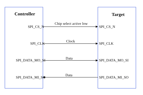
Figure : SPI data flow</strong></p>

The SPI core supports the bidirectional SPI standard, point-to-point, and controller-target protocol. The SPI core uses four chip‑select lines (SPI\_CS#\_N) to select target devices for communication. The following two data lines support the bidirectional data transfer.

* SPI\_DATA\_MO\_SI: Controller data output, target data input.
* SPI\_DATA\_MI\_SO: Controller data input, target data output.

**Table :**

**Data and control signals in SPI**

<table style={tblA}>
  <tbody>
    <tr>
      <td rowSpan="2" style={tdA}>Data signals</td>
      <td style={tdA}>MOSI: Controller data output, target data input.</td>
    </tr>

    <tr>
      <td style={tdA}>MISO: Controller data input, target data output.</td>
    </tr>

    <tr>
      <td rowSpan="2" style={tdA}>Control signals</td>
      <td style={tdA}>SCLK: A clock generated by the controller and input to all targets.</td>
    </tr>

    <tr>
      <td style={tdA}>CS: Chip-select, a target is selected when the controller asserts its CS\_N signal.</td>
    </tr>
  </tbody>
</table>

## **SPI features**

This section explains the SPI serial engine transfer modes and the different scenarios where each mode is used. This section also describes the FIFO and DMA enabled in various subsystem SPI drivers.

**Table :**

**SPI transfer modes**

<table style={tblA}>
  <thead>
    <tr>
      <th style={thAeq}>Subsystem</th>
      <th style={thAeq}>Transfer mode</th>
      <th style={thAeq}>Description</th>
    </tr>
  </thead>

  <tbody>
    <tr>
      <td style={tdA}>Linux</td>

      <td style={tdA}>
        <ul>
          <li>FIFO (low speed)</li>
          <li>CPU DMA (high speed)</li>
          <li>GSI</li>
        </ul>
      </td>

      <td style={tdA}>Supports a maximum configuration speed of 50 MHz.</td>
    </tr>

    <tr>
      <td style={tdA}>Boot</td>
      <td style={tdA}>FIFO</td>

      <td style={tdA}>
        <ul>
          <li>Transfer rates up to 50 MHz. The host sets the SPI clock frequency nearest to the requested frequency.</li>
          <li>4 bits to 32 bits per word of transfer.</li>
          <li>Maximum of 4 chip selects (CS) per bus.</li>
          <li>GSI mode isn't supported on boot.</li>
          <li>The driver executes in polling mode.</li>
        </ul>
      </td>
    </tr>

    <tr>
      <td style={tdA}>aDSP</td>

      <td style={tdA}>
        <ul>
          <li>Full duplex</li>
          <li>Half duplex</li>
          <li>Synchronous</li>
          <li>Serial communication</li>
        </ul>
      </td>

      <td style={tdA}>
        <ul>
          <li>There is no explicit communication framing, error checking, or defined data word length.</li>
          <li>The communication is strictly at the raw bit level.</li>
          <li>Transfer rates up to 50 MHz. The host sets the SPI clock frequency nearest to the requested frequency.</li>
          <li>4 bits to 32 bits per word of transfer.</li>
          <li>Maximum of 4 chip selects (CS) per bus.</li>
        </ul>
      </td>
    </tr>
  </tbody>
</table>

## **SPI interface components**

This section provides information about the subsystem drivers, kernel device tree nodes, and related documentation.

**Table :**

**SPI interface: Linux**

<table style={tblA}>
  <thead>
    <tr>
      <th style={thA1}>File type</th>
      <th style={thA2}>Description</th>
    </tr>
  </thead>

  <tbody>
    <tr>
      <td style={tdA}>Device tree source</td>

      <td style={tdA}>
        <ul>
          <li>QCS6490 and QCS5430: [https://git.linaro.org/kernel-org/linux-next.git/tree/arch/arm64/boot/dts/qcom/sc7280.dtsi](https://git.linaro.org/kernel-org/linux-next.git/tree/arch/arm64/boot/dts/qcom/sc7280.dtsi)</li>
          <li>Dragonwing IQ-9075: [https://github.com/torvalds/linux/blob/master/arch/arm64/boot/dts/qcom/sa8775p.dtsi](https://github.com/torvalds/linux/blob/master/arch/arm64/boot/dts/qcom/sa8775p.dtsi)</li>
          <li>Dragonwing IQ-615: [https://git.kernel.org/pub/scm/linux/kernel/git/qcom/linux.git/tree/arch/arm64/boot/dts/qcom/qcs615.dtsi?h=arm64-for-6.16](https://git.kernel.org/pub/scm/linux/kernel/git/qcom/linux.git/tree/arch/arm64/boot/dts/qcom/qcs615.dtsi?h=arm64-for-6.16)</li>
          <li>For information about QUP v3 serial engine device nodes, see the kernel documentation at [https://github.com/torvalds/linux/blob/master/Documentation/devicetree/bindings/spi/qcom%2Cspi-geni-qcom.yaml](https://github.com/torvalds/linux/blob/master/Documentation/devicetree/bindings/spi/qcom%2Cspi-geni-qcom.yaml)</li>
        </ul>
      </td>
    </tr>

    <tr>
      <td style={tdA}>`Pinctrl` settings</td>

      <td style={tdA}>
        <ul>
          <li>QCS6490 and QCS5430: [https://git.linaro.org/kernel-org/linux-next.git/tree/arch/arm64/boot/dts/qcom/sc7280.dtsi](https://git.linaro.org/kernel-org/linux-next.git/tree/arch/arm64/boot/dts/qcom/sc7280.dtsi)</li>
          <li>Dragonwing IQ-9075: [https://github.com/torvalds/linux/blob/master/arch/arm64/boot/dts/qcom/sa8775p.dtsi](https://github.com/torvalds/linux/blob/master/arch/arm64/boot/dts/qcom/sa8775p.dtsi)</li>
          <li>Dragonwing IQ-615: [https://git.kernel.org/pub/scm/linux/kernel/git/qcom/linux.git/tree/arch/arm64/boot/dts/qcom/qcs615.dtsi?h=arm64-for-6.16](https://git.kernel.org/pub/scm/linux/kernel/git/qcom/linux.git/tree/arch/arm64/boot/dts/qcom/qcs615.dtsi?h=arm64-for-6.16)</li>
        </ul>
      </td>
    </tr>

    <tr>
      <td style={tdA}>Qualcomm TEE settings</td>

      <td style={tdA}>
        <ul>
          <li>`/firmware/qualcomm-linux-spf-1-0_ap_standard_oem_nomodem/TZ.XF.5.0/trustzone_images/core/settings/buses/qup_accesscontrol/qupv3/config/<chipset>/QUPAC_Access.c`</li>
        </ul>
      </td>
    </tr>
  </tbody>
</table>

**Table :**

**SPI interface: Boot**

<table style={tblA}>
  <thead>
    <tr>
      <th style={thA1}>File type</th>
      <th style={thA2}>Description</th>
    </tr>
  </thead>

  <tbody>
    <tr>
      <td style={tdA}>QUP v3 serial engine configuration</td>

      <td style={tdA}>
        <ul>
          <li>QUP v3 serial engine: `/firmware/qualcomm-linux-spf-1-0_ap_standard_oem_nomodem/BOOT.MXF.1.0.c1/boot_images/boot/Settings/Soc/<chipset>/Core/Buses/qup_common/<chipset>-qupv3.dtsi`</li>
          <li>GPIO configurations: `/firmware/qualcomm-linux-spf-1-0_ap_standard_oem_nomodem/BOOT.MXF.1.0.c1/boot_images/boot/Settings/Soc/<chipset>/Core/Buses/qup_common/<chipset>-qupv3-pinctrl.dtsi`</li>
        </ul>
      </td>
    </tr>

    <tr>
      <td style={tdA}>Qualcomm TEE settings</td>

      <td style={tdA}>
        <ul>
          <li>`/firmware/qualcomm-linux-spf-1-0_ap_standard_oem_nomodem/TZ.XF.5.0/trustzone_images/core/settings/buses/qup_accesscontrol/qupv3/config/<chipset>/QUPAC_Access.c`</li>
        </ul>
      </td>
    </tr>
  </tbody>
</table>

**Table :**

**SPI interface: aDSP/SLPI/SDC**

<table style={tblA}>
  <thead>
    <tr>
      <th style={thA1}>File type</th>
      <th style={thA2}>Description</th>
    </tr>
  </thead>

  <tbody>
    <tr>
      <td style={tdA}>QUP v3 serial engine configuration</td>

      <td style={tdA}>
        <ul>
          <li>`/firmware/qualcomm-linux-spf-1-0_ap_standard_oem_nomodem/ADSP.HT.5.5.c8/adsp_proc/core/settings/buses/qup_common/config/<chipset>/adsp/ssc/qup_devcfg.c`</li>
          <li>`/firmware/qualcomm-linux-spf-1-0_ap_standard_oem_nomodem/ADSP.HT.5.5.c8/adsp_proc/core/settings/buses/qup_fw/config/<chipset>/fw_devcfg.c`</li>
          <li>`settings/buses/qup_common/config/<chipset>/adsp/ssc/qup_devcfg.json`</li>
        </ul>
      </td>
    </tr>

    <tr>
      <td style={tdA}>Firmware configuration settings</td>

      <td style={tdA}>
        <ul>
          <li>`/firmware/qualcomm-linux-spf-1-0_ap_standard_oem_nomodem/ADSP.HT.5.5.c8/adsp_proc/core/settings/buses/qup_fw/config/<chipset>/fw_devcfg.c`</li>
          <li>`/firmware/qualcomm-linux-spf-1-0_ap_standard_oem_nomodem/ADSP.HT.5.5.c8/adsp_proc/core/settings/buses/qup_fw/config/<chipset>/fw_devcfg.xml`</li>
        </ul>
      </td>
    </tr>
  </tbody>
</table>

**Table :**

**SPI interface: Qualcomm TEE**

<table style={tblA}>
  <thead>
    <tr>
      <th style={thA1}>File type</th>
      <th style={thA2}>Description</th>
    </tr>
  </thead>

  <tbody>
    <tr>
      <td style={tdA}>QUP v3 serial engine configuration</td>

      <td style={tdA}>
        <ul>
          <li>`/firmware/qualcomm-linux-spf-1-0_ap_standard_oem_nomodem/TZ.XF.5.0/trustzone_images/core/settings/buses/spi/qupv3/config/<chipset>/tz/spi_devcfg_user.c`</li>
          <li>`/firmware/qualcomm-linux-spf-1-0_ap_standard_oem_nomodem/TZ.XF.5.0/trustzone_images/core/settings/buses/spi/qupv3/config/<chipset>/tz/spi_devcfg_user.h`</li>
          <li>`/firmware/qualcomm-linux-spf-1-0_ap_standard_oem_nomodem/TZ.XF.5.0/trustzone_images/core/settings/buses/spi/qupv3/config/<chipset>/tz/spi_devcfg.xml`</li>
        </ul>
      </td>
    </tr>

    <tr>
      <td style={tdA}>Qualcomm TEE settings</td>

      <td style={tdA}>
        <ul>
          <li>`/firmware/qualcomm-linux-spf-1-0_ap_standard_oem_nomodem/TZ.XF.5.0/trustzone_images/core/settings/buses/qup_accesscontrol/qupv3/config/<chipset>/QUPAC_Access.c`</li>
        </ul>
      </td>
    </tr>
  </tbody>
</table>

### **SPI APIs**

SPI APIs for the following subsystems are listed in this section.

* Linux:
  * [https://github.com/torvalds/linux/blob/master/include/uapi/linux/spi/spidev.h](https://github.com/torvalds/linux/blob/master/include/uapi/linux/spi/spidev.h).
  * [https://github.com/torvalds/linux/blob/master/include/linux/spi/spi.h](https://github.com/torvalds/linux/blob/master/include/linux/spi/spi.h).
* Boot: boot\_images/boot/QcomPkg/Include/SpiApi.h
* aDSP/SDC: adsp\_proc/core/api/buses/spi\_api.h

## **SPI software device tree configuration**

This section provides information on the SPI device tree configuration and documentation for the device nodes.

### **Linux**

For device SPI details, see the following DTSI files.

* QCS6490 and QCS5430: [https://git.linaro.org/kernel-org/linux-next.git/tree/arch/arm64/boot/dts/qcom/sc7280.dtsi](https://git.linaro.org/kernel-org/linux-next.git/tree/arch/arm64/boot/dts/qcom/sc7280.dtsi)
* Dragonwing IQ-9075: [https://github.com/torvalds/linux/blob/master/arch/arm64/boot/dts/qcom/sa8775p.dtsi](https://github.com/torvalds/linux/blob/master/arch/arm64/boot/dts/qcom/sa8775p.dtsi)
* Dragonwing IQ-615: [https://git.kernel.org/pub/scm/linux/kernel/git/qcom/linux.git/tree/arch/arm64/boot/dts/qcom/qcs615.dtsi?h=arm64-for-6.16](https://git.kernel.org/pub/scm/linux/kernel/git/qcom/linux.git/tree/arch/arm64/boot/dts/qcom/qcs615.dtsi?h=arm64-for-6.16)

For more information about kernel documentation specific to the SPI device nodes, see [https://github.com/torvalds/linux/blob/master/Documentation/devicetree/bindings/spi/qcom%2Cspi-geni-qcom.yaml](https://github.com/torvalds/linux/blob/master/Documentation/devicetree/bindings/spi/qcom%2Cspi-geni-qcom.yaml), and SPI driver file at [https://github.com/torvalds/linux/blob/master/drivers/spi/spi-geni-qcom.c](https://github.com/torvalds/linux/blob/master/drivers/spi/spi-geni-qcom.c).

```text theme={null}
spi@a98000 {
compatible = "qcom,geni-spi";
reg = <0 0x00a98000 0 0x4000>;
clocks = <&gcc GCC_QUPV3_WRAP1_S6_CLK>;
clock-names = "se";
pinctrl-names = "default";
pinctrl-0 = <&qup_spi14_data_clk>, <&qup_spi14_cs>;
interrupts = <GIC_SPI 368 IRQ_TYPE_LEVEL_HIGH>;
#address-cells = <1>;
#size-cells = <0>;
power-domains = <&rpmhpd SC7280_CX>;
operating-points-v2 = <&qup_opp_table>;
interconnects = <&clk_virt MASTER_QUP_CORE_1 0 &clk_virt SLAVE_QUP_CORE_1 0>,
		<&gem_noc MASTER_APPSS_PROC 0 &cnoc2 SLAVE_QUP_1 0>;
interconnect-names = "qup-core", "qup-config";
		dmas = <&gpi_dma1 0 6 QCOM_GPI_SPI>,
	       <&gpi_dma1 1 6 QCOM_GPI_SPI>;
dma-names = "tx", "rx";
status = "disabled";
};
```

For kernel documentation specific to the GPIO `pinctrl` configuration, see the following files.

* QCS6490 and QCS5430: [https://git.linaro.org/kernel-org/linux-next.git/tree/arch/arm64/boot/dts/qcom/sc7280.dtsi](https://git.linaro.org/kernel-org/linux-next.git/tree/arch/arm64/boot/dts/qcom/sc7280.dtsi)
* Dragonwing IQ-9075: [https://github.com/torvalds/linux/blob/master/arch/arm64/boot/dts/qcom/sa8775p.dtsi](https://github.com/torvalds/linux/blob/master/arch/arm64/boot/dts/qcom/sa8775p.dtsi)
* Dragonwing IQ-615: [https://git.kernel.org/pub/scm/linux/kernel/git/qcom/linux.git/tree/arch/arm64/boot/dts/qcom/qcs615.dtsi?h=arm64-for-6.16](https://git.kernel.org/pub/scm/linux/kernel/git/qcom/linux.git/tree/arch/arm64/boot/dts/qcom/qcs615.dtsi?h=arm64-for-6.16)
* `Documentation/devicetree/bindings/pinctrl/qcom,<chipset>-tlmm.yaml`

The corresponding configurations of the QUP v3 serial engine GPIOs are present and mapped in the `pinctrl.dtsi`.

For example:

```text theme={null}
qup_spi14_data_clk: qup-spi14-data-clk-state {
				pins = "gpio56", "gpio57", "gpio58";
				function = "qup16";
			};

			qup_spi14_cs: qup-spi14-cs-state {
				pins = "gpio59";
				function = "qup16";
			};

			qup_spi14_cs_gpio: qup-spi14-cs-gpio-state {
				pins = "gpio59";
				function = "gpio";
			};

			qup_spi15_data_clk: qup-spi15-data-clk-state {
				pins = "gpio60", "gpio61", "gpio62";
				function = "qup17";
			};
```

Ensure that the protocol configuration for a particular serial engine uses the SPI protocol in the file at `/firmware/qualcomm-linux-spf-1-0_ap_standard_oem_nomodem/TZ.XF.5.0/trustzone_images/core/settings/buses/qup_accesscontrol/qupv3/config/<chipset>/QUPAC_Access.c`. Modify the required settings if needed or see the default settings assigned for QUP v3 serial engine instances.

Following is the sample configuration for enabling the SPI.

```text theme={null}

{ QUPV3_0_SE3, QUPV3_PROTOCOL_SPI,     QUPV3_MODE_FIFO, AC_HLOS,            TRUE,  TRUE,  FALSE }, // CAN SPI
{ QUPV3_1_SE3, QUPV3_PROTOCOL_SPI,     QUPV3_MODE_FIFO, AC_HLOS,            FALSE, TRUE,  TRUE }, // LS1 SPI
{ QUPV3_1_SE4, QUPV3_PROTOCOL_SPI,     QUPV3_MODE_GSI,  AC_TZ,              FALSE, TRUE,  TRUE }, // SPI -NFC ESE
{ QUPV3_1_SE6, QUPV3_PROTOCOL_SPI,     QUPV3_MODE_GSI,  AC_HLOS,            FALSE, TRUE,  FALSE}, // FP
{ QUPV3_SSC_SE2, QUPV3_PROTOCOL_SPI,     QUPV3_MODE_GSI, AC_ADSP_Q6_ELF,  FALSE,      FALSE, FALSE }, // IMU_SPI
```

### **Boot**

Configure the QUP v3 settings according to the Qualcomm Linux chip product requirements in the `/firmware/qualcomm-linux-spf-1-0_ap_standard_oem_nomodem/BOOT.MXF.1.0.c1/boot_images/boot/Settings/Soc/<chipset>/Core/Buses/qup_common/<chipset>-qupv3.dtsi` file.

<Note>
  **Note**

  To enable the required QUP v3 serial engine, update the QUP v3 wrapper node status to `okay`, and the respective serial engine node to `disabled` state.
</Note>

The following sample nodes help to configure the QUP v3 serial engine in boot.

**QUP wrapper node sample**

```text theme={null}
       /* QUPV3_0  wrapper  instance */
    TOP_QUP_0{ 
        compatible = "qcom,qup-controller";
        qup_id                      = /bits/  8 <(QUP_0)>;
        core_base_addr              = <QUPV3_0_CORE_BASE_ADDRESS>;
        common_base_addr            = <(QUPV3_0_CORE_COMMON_BASE_ADDRESS)>;
        se_wrapper_base_addr        = <(QUPV3_0_CORE_SE_BASE_ADDRESS)>;
        core_frequency              = <100000000>;
        qup_flags                   = <(QUP_FLAGS_UNUSED)>;
        num_se                      = /bits/ 8 <8>;
        status                      = "okay"; 
```

**Sample node of serial engine instance**

```text theme={null}
/*TOP_QUP_0_SE_0  Instance */ 
        TOP_QUP_0_SE_0{
          status                      = "disabled";  (updated to okay if you need the instance to be enabled)
            core_offset                 = <0x00000000>;
            se_flags                    = <(USES_DDR_BUFFER | USES_INTERNAL_DDR_MEM | ENABLE_FATAL_ON_TIMEOUT | POLLED_MODE)>;
            se_index                    = /bits/  8 <0>;
            FIFO_MODE                   = /bits/  8 <1>;
            protocol_supported          = <(I2C_SUPPORTED | UART_SUPPORTED | SPI_SUPPORTED)>;
            interface_supported         = <CORE_IRQ>;
           * gpi_index                   = /bits/ 8 <0xFF>;
            core_irq                    = /bits/ 16 <0>;
            pdc_irq                     = /bits/ 16 <0>;
            gpio_int_num                = /bits/ 16 <0>;
            i2c_hub                     = /bits/ 8  <0>;
            i2c_mm                      = /bits/ 16 <0>;
            SE_EXCLUSIVE                = /bits/  8 <1>;
            pinctrl-names               = "i2c-default", "i2c-sleep","spi-default", "spi-sleep","uart-default", "uart-sleep";
            pinctrl-0                   = <&top_qup0_se0_i2c_active>;
            pinctrl-1                   = <&top_qup0_se0_i2c_sleep>;
            pinctrl-2                   = <&top_qup0_se0_spi_active>;
            pinctrl-3                   = <&top_qup0_se0_spi_sleep>;
            pinctrl-4                   = <&top_qup0_se0_uart_active>;
            pinctrl-5                   = <&top_qup0_se0_uart_sleep>;

            se_clock                    = "gcc_qupv3_wrap0_s0_clk";
        };
```

For `pinctrl` definitions, see the GPIO configuration file at `/firmware/qualcomm-linux-spf-1-0_ap_standard_oem_nomodem/BOOT.MXF.1.0.c1/boot_images/boot/Settings/Soc/<chipset>/Core/Buses/qup_common/<chipset>-qupv3-pinctrl.dtsi`.

Sample GPIO configuration:

```text theme={null}
#define top_qup0_se1_i2c_active_cfg  GPIO_CFG(GPIO_INPUT,GPIO_PULL_UP,GPIO_DRIVE_STRENGTH(200),GPIO_STRONG_PULL)
```

* In `<chipset>-qupv3-pinctrl.dtsi` modify the macro with the GPIO configuration when the requirements are different from the default configuration.
* For the macro definition, see the header file path at `Settings/Include/gpio-dt.h`.

Replace macro in sample TLMM node.

```text theme={null}
  /*TOP_QUP0_se1_pinctrl*/
    top_qup0_se1_i2c_active: top_qup0_se1_i2c_active{
    --    config = <&qup0_l0_1 top_qup_i2c_active_cfg>,
                 <&qup0_l1_1 top_qup_i2c_active_cfg>;
   ++  config = <&qup0_l0_1 top_qup0_se1_i2c_active_cfg>,
                 <&qup0_l1_1 top_qup0_se1_i2c_active_cfg>;
    };
```

<Note>
  **Note**

  Verify Qualcomm TEE settings before changing the unified extensible firmware interface (UEFI) configuration. Ensure that the serial engine node is in FIFO\_MODE and accessible from the application processor. Verify that the loaded protocol is according to the requirement.
</Note>

### **aDSP/SDC**

The firmware loads SSC QUP during the bootup sequence of the aDSP subsystem. The configuration file is present in the aDSP build at `/firmware/qualcomm-linux-spf-1-0_ap_standard_oem_nomodem/ADSP.HT.5.5.c8/adsp_proc/core/settings/buses/qup_fw/config/<chipset>/fw_devcfg.c` and `/firmware/qualcomm-linux-spf-1-0_ap_standard_oem_nomodem/ADSP.HT.5.5.c8/adsp_proc/core/settings/buses/qup_fw/config/<chipset>/fw_devcfg.xml`.

The following configuration is a sample of the SSC QUP SE4 loaded with the SPI firmware.

```text theme={null}
se_cfg se4_cfg = { 0x90000, SE_PROTOCOL_SPI,   	GSI,     TRUE, TRUE };
```

**GPIO configuration**: Each serial engine in the QUP common driver is configured with the default GPIO configuration. The GPIO configuration is picked up by the QUP common driver according to the protocol loaded for the serial engine at `/firmware/qualcomm-linux-spf-1-0_ap_standard_oem_nomodem/ADSP.HT.5.5.c8/adsp_proc/core/settings/buses/qup_common/config/<chipset>/adsp/ssc/qup_instance_mapping.c`.

The default GPIO configuration can be overwritten as follows.

```text theme={null}
{      .instance_id          =  5 ,         //Instance ID
        .qup              =  QUP_SSC,    //QUP Type
        .se_index         =  4,          //SE ID
        .se_data          =  NULL,       //devcfg_map
        .protocol_io_cfg  =  {
                                TLMM_MAP(TLMM_GPIO_KEEPER ,TLMM_GPIO_2MA,TLMM_GPIO_KEEPER ),              //SLEEP CFG
                                TLMM_MAP(TLMM_GPIO_NO_PULL,TLMM_GPIO_6MA,TLMM_GPIO_KEEPER ),              //SPI CFG
                                TLMM_MAP(TLMM_GPIO_NO_PULL,TLMM_GPIO_2MA,TLMM_GPIO_NO_PULL),              //UART CFG
                                TLMM_MAP(TLMM_GPIO_PULL_UP,TLMM_GPIO_2MA,TLMM_GPIO_NO_PULL),              //I2C CFG
                                TLMM_MAP(TLMM_GPIO_PULL_UP,TLMM_GPIO_2MA,TLMM_GPIO_KEEPER )               //I3C CFG
                             },
        .se_exclusive     =  TRUE,
}
```

TLMM\_MAP is a macro to initialize the active and sleep state GPIO configurations. For example, sample usage of the TLMM\_MAP macro.

```text theme={null}
TLMM_MAP (active state pull type, drive strength, sleep state pull type)
```

### **Qualcomm TEE**

The QUP v3 access configuration settings are at `/firmware/qualcomm-linux-spf-1-0_ap_standard_oem_nomodem/TZ.XF.5.0/trustzone_images/core/settings/buses/spi/qupv3/interface/spi_devcfg.h`.

To enable the QUP v3 serial engine for SPI in `/firmware/qualcomm-linux-spf-1-0_ap_standard_oem_nomodem/TZ.XF.5.0/trustzone_images/core/settings/buses/spi/qupv3/config/<chipset>/tz/spi_devcfg_user.h`, add `#define TZ_USE_SPI_X` (X is the SPI serial engine number) as follows.

```text theme={null}
#define TZ_USE_SPI_13 //NFC-ese
```

```text theme={null}
#define TZ_USE_SPI_14 //Touch-SPI
```

```text theme={null}
#define TZ_USE_SPI_15 //FP sensor
```

The `TZ_USE_SPI_<num>` number is based on the serial number of the serial engine (starting from one). For example, if there are two QUPs: QUPV3\_0 with seven serial engines and QUPV3\_1 with eight serial engines, the user must enable QUPV3\_2\_SE2. The macro should be TZ\_USE\_SPI\_9.

**GPIO configuration**: In the following example, drive strength and pull are configured according to the PIN starting index from MISO at `settings/buses/spi/qupv3/config/<chipset>/tz/spi_devcfg_user.c`.

```text theme={null}
spi_plat_device_config_user spi_device_user_config_0 =
 
    {2,2,2,2,-1,-1,-1},    //.drive_strength index: 0 - MISO, 1 - MOSI, 2 - SCLK, 3 - CS_0, 4- CS_1, 5- CS_2, 6- CS_3
                                	                 value: 0 - 2MA, 1 - 4MA, 2 - 6MA
    {1,1,0,1,-1,-1,-1},    //.pull index: 0 - MISO, 1 - MOSI, 2 - SCLK, 3 - CS_0, 4- CS_1, 5- CS_2, 6- CS_3
                                value: 0 - NO_PULL, 1 = PULL_DOWN, 2 = KEEPER, 3 = PULL_UP
    0xFF,                 //.gpii_idx 
    0,                   //.mode_select  not supported for TZ
    0,                   //.flags not supported for TZ
};
```

Access control permission to the Qualcomm TEE subsystem is configured in the QUPAC policy at `/firmware/qualcomm-linux-spf-1-0_ap_standard_oem_nomodem/TZ.XF.5.0/trustzone_images/core/settings/buses/qup_accesscontrol/qupv3/config/<chipset>/QUPAC_Access.c`.

```text theme={null}
const QUPv3_se_security_permissions_type qupv3_perms_iot_rb3[] =
{
  /*   PeriphID,         ProtocolID,               Mode,  NsOwner,       bAllowFifo, bLoad, bModExcl  */
  { QUPV3_0_SE0, QUPV3_PROTOCOL_I2C,     QUPV3_MODE_FIFO, AC_HLOS,            TRUE,  TRUE,  FALSE }, // LT9611 and QPS615 I2C
  { QUPV3_0_SE1, QUPV3_PROTOCOL_I2C,     QUPV3_MODE_FIFO, AC_HLOS,            TRUE,  TRUE,  FALSE }, // APPS I2C - PCIE/ USB Type C
  { QUPV3_0_SE2, QUPV3_PROTOCOL_I2C,     QUPV3_MODE_FIFO, AC_HLOS,            TRUE,  TRUE,  FALSE }, // SMB / LS1 I2C
  { QUPV3_0_SE3, QUPV3_PROTOCOL_SPI,     QUPV3_MODE_FIFO, AC_HLOS,            TRUE,  TRUE,  FALSE }, // CAN SPI
  { QUPV3_0_SE4, QUPV3_PROTOCOL_UART_4W, QUPV3_MODE_FIFO, AC_HLOS,            TRUE,  TRUE,  FALSE }, // LS1 UART
  { QUPV3_0_SE5, QUPV3_PROTOCOL_UART_2W, QUPV3_MODE_FIFO, AC_HLOS,            TRUE,  FALSE, FALSE }, // Debug UART
  { QUPV3_0_SE6, QUPV3_PROTOCOL_UART_2W, QUPV3_MODE_FIFO, AC_HLOS,            TRUE,  TRUE,  FALSE }, // WLAN UART
  { QUPV3_0_SE7, QUPV3_PROTOCOL_UART_4W, QUPV3_MODE_FIFO, AC_HLOS,            TRUE,  TRUE,  FALSE }, // Hastings BT
  { QUPV3_1_SE0, QUPV3_PROTOCOL_SPMI,    QUPV3_MODE_FIFO, AC_ADSP_Q6_ELF,     TRUE,  TRUE,  FALSE }, // QuP SPMI
  { QUPV3_1_SE1, QUPV3_PROTOCOL_I2C,     QUPV3_MODE_FIFO, AC_HLOS,            TRUE,  TRUE,  FALSE }, // NFC I2C
  { QUPV3_1_SE2, QUPV3_PROTOCOL_I2C,     QUPV3_MODE_FIFO, AC_HLOS,            TRUE,  TRUE,  FALSE }, // HDMI OUT for VIDEOIOBoard
  { QUPV3_1_SE3, QUPV3_PROTOCOL_SPI,     QUPV3_MODE_FIFO, AC_HLOS,            FALSE, TRUE,  TRUE }, // LS1 SPI
  { QUPV3_1_SE4, QUPV3_PROTOCOL_SPI,     QUPV3_MODE_GSI,  AC_TZ,              FALSE, TRUE,  TRUE }, // SPI -NFC ESE
  { QUPV3_1_SE5, QUPV3_PROTOCOL_I2C,     QUPV3_MODE_GSI,  AC_HLOS,            FALSE, TRUE,  FALSE}, // Legacy Touch
  { QUPV3_1_SE6, QUPV3_PROTOCOL_SPI,     QUPV3_MODE_GSI,  AC_HLOS,            FALSE, TRUE,  FALSE}, // FP
  /*QUPV3_1_SE7*/
};
```

## **SPI bringup**

This section describes how to enable the Qualcomm Linux SPI drivers.

### **Linux**

To verify SPI communication with the device, kernel configuration must be enabled. The `CONFIG_SPI_SPIDEV=m` setting is enabled in the corresponding `<chipset> defconfig` file. Enable the specific QUP v3 SPI serial engine instance in the kernel device tree.

## **SPI configuration**

This section provides information about the SPI software driver kernel configuration and device tree node changes.

### **Linux**

The following driver kernel configurations are required to support the SPI interface.

* Driver source file at [https://github.com/torvalds/linux/blob/master/drivers/spi/spi-geni-qcom.c](https://github.com/torvalds/linux/blob/master/drivers/spi/spi-geni-qcom.c)
* Kernel `defconfig` file at `<workspace_path_of_LINUX_kernel_image>/sources/kernel/kernel_platform/kernel/arch/arm64/configs/qcom_defconfig`

The following kernel configurations must be enabled.

* `CONFIG_QCOM_GENI_SE=y`
* `CONFIG_SPI_QCOM_GENI=m`
* `CONFIG_SPI_SPIDEV=m` to configure user space applications
* `CONFIG_QCOM_GPI_DMA=m` to enable GSI support

To enable the SPI node for the loopback validation, apply the following patch to the `/arch/arm64/boot/dts/qcom/<chipset>.dtsi` file.

```text theme={null}
diff --git a/arch/arm64/boot/dts/qcom/<chipset>.dtsi b/arch/arm64/boot/dts/qcom/<chipset>.dtsi
index 82dfa3e..344e99a 100644
--- a/arch/arm64/boot/dts/qcom/<chipset>.dtsi
+++ b/arch/arm64/boot/dts/qcom/<chipset>.dtsi
@@ -6760,3 +6760,12 @@
<GIC_PPI 10 IRQ_TYPE_LEVEL_LOW>;
 };
 };
+
+&spi14 {
+        status = "ok";
+        spidev@0 {
+                compatible = "spidev";
+                spi-max-frequency = <50000000>;
+                reg = <0>;
+        };
+};

diff --git a/drivers/spi/spidev.c b/drivers/spi/spidev.c
index d13dc15..36d7914 100644
--- a/drivers/spi/spidev.c
+++ b/drivers/spi/spidev.c
@@ -84,7 +84,7 @@
static LIST_HEAD(device_list);
static DEFINE_MUTEX(device_list_lock);
 
-static unsigned bufsiz = 4096;
+static unsigned bufsiz = 35000;
module_param(bufsiz, uint, S_IRUGO);
MODULE_PARM_DESC(bufsiz, "data bytes in biggest supported SPI message");
 
@@ -742,6 +742,7 @@
 	{ .compatible = "semtech,sx1301", .data = &spidev_of_check },
 	{ .compatible = "silabs,em3581", .data = &spidev_of_check },
 	{ .compatible = "silabs,si3210", .data = &spidev_of_check },
+	{ .compatible = "spidev"},
{},
 };
 MODULE_DEVICE_TABLE(of, spidev_dt_ids);
```

<Note>
  **Note**

  You should compile the kernel configuration and device tree changes. After the kernel is compiled, you can load the images to the device to verify the interface. For information about interface verification, see the [SPI verification](https://dragonwingdocs.qualcomm.com/System/Interfaces/spi#spi-verification) section.
</Note>

## **SPI verification**

This section describes the validation procedure and test results for the SPI drivers.

### **Linux**

To cross-compile the SPI tools, do the following.

1. Access the SPI tool from `yocto/build-qcom-wayland/tmp-glibc/work-shared/<chipset>/kernel-source/tools/spi`. For more details about the SPI tool, see [https://git.kernel.org/pub/scm/linux/kernel/git/stable/linux.git/tree/tools/spi](https://git.kernel.org/pub/scm/linux/kernel/git/stable/linux.git/tree/tools/spi).
2. Install cross compiler.
   ```text theme={null}
   sudo apt-get install gcc-aarch64-linux-gnu
   ```
3. Set up the environment for cross-compilation by running the following command.
   ```text theme={null}
   export ARCH=arm64
   export CROSS_COMPILE=aarch64-linux-gnu-
   ```
4. Compile the tool by running the following command.
   ```text theme={null}
   make
   ```

### **Verify SPI device**

Verify the driver by checking for `dev` node (`/dev/spidev1.0`) in the SSH shell or use the ADB shell. For more information about how to run SSH, see the [Use SSH](https://docs.qualcomm.com/bundle/publicresource/topics/80-80021-254/how_to.html) section.

1. To verify the SPI driver, do the following:
   1. Open the SSH shell in permissive mode or use the ADB shell.
   2. Mount the file system.
      ```text theme={null}
      mount -o remount,rw /usr
      ```
   3. Transfer files using SCP or similar tools.
      For example, `scp spidev_test root@10.92.175.138:/bin`.
   4. Assign permission to execute.
      ```text theme={null}
      chmod 777 spidev_test
      ```
2. Verify an SPI device. Command format `./spidev_test -D /dev/<spidev_node>`.
   ```text theme={null}
   ./spidev_test -D /dev/spidev1.0
   ./spidev_test -D /dev/spidev3.0
   ```
   The following output is displayed.
   ```text theme={null}
   spi mode: 0x0
   bits per word: 8
   max speed: 500000 Hz (500 KHz)
   ```

Run the following command for information about usage.

```text theme={null}
./spidev_test -help
```

The following output is displayed.

```text theme={null}
-D --device   device to use (default /dev/spidev1.1)
-s --speed    max speed (Hz)
-d --delay    delay (usec)
-b --bpw      bits per word
-i --input    input data from a file (e.g. "test.bin")
-o --output   output data to a file (e.g. "results.bin")
-l --loop     loopback
-H --cpha     clock phase
-O --cpol     clock polarity
-L --lsb      least significant bit first
-C --cs-high  chip select active high
-3 --3wire    SI/SO signals shared
-v --verbose  Verbose (show tx buffer)
-p  Send data (e.g. "1234\xde\xad")
-N --no-cs    no chip select
  -R --ready    slave pulls low to pause
  -2 --dual     dual transfer
  -4 --quad     quad transfer
  -8 --octal    octal transfer
  -S --size     transfer size
  -I --iter     iterations
```

## **SPI debugging**

This section describes the default logging method of the SPI software driver to enable logging the SPI transfer failures.

### **Linux**

The SPI driver logs are enabled through a dynamic debugging method. Enable `CONFIG_DYNAMIC_DEBUG` in `<workspace_path_of_LINUX_kernel_image>/sources/kernel/kernel_platform/kernel/arch/arm64/configs/qcom_defconfig` to support the dynamic debugging of the kernel drivers.

To enable and view the SPI driver logs in the kernel logs (`dmesg`), run the following command.

```text theme={null}
mount -t debugfs none /sys/kernel/debug
echo -n "file spi-geni-qcom.c +p" > /sys/kernel/debug/dynamic_debug/control
echo -n "file qcom-geni-se.c  +p" > /sys/kernel/debug/dynamic_debug/control
echo -n "file spidev.c +p" > /sys/kernel/debug/dynamic_debug/control
echo -n "file gpi.c +p" > /sys/kernel/debug/dynamic_debug/control
```

## **SPI examples**

For information about the upstream device tree reference, see the following DTSI files.

* QCS6490 and QCS5430: [https://git.linaro.org/kernel-org/linux-next.git/tree/arch/arm64/boot/dts/qcom/sc7280.dtsi](https://git.linaro.org/kernel-org/linux-next.git/tree/arch/arm64/boot/dts/qcom/sc7280.dtsi)
* Dragonwing IQ-9075: [https://github.com/torvalds/linux/blob/master/arch/arm64/boot/dts/qcom/sa8775p.dtsi](https://github.com/torvalds/linux/blob/master/arch/arm64/boot/dts/qcom/sa8775p.dtsi)
* Dragonwing IQ-615: [https://git.kernel.org/pub/scm/linux/kernel/git/qcom/linux.git/tree/arch/arm64/boot/dts/qcom/qcs615.dtsi?h=arm64-for-6.16](https://git.kernel.org/pub/scm/linux/kernel/git/qcom/linux.git/tree/arch/arm64/boot/dts/qcom/qcs615.dtsi?h=arm64-for-6.16)

For information about device-tree node for the Qualcomm Linux hardware SoCs, see the following DTSI files.

* QCS6490 and QCS5430: [https://git.linaro.org/kernel-org/linux-next.git/tree/arch/arm64/boot/dts/qcom/qcs6490-rb3gen2.dts](https://git.linaro.org/kernel-org/linux-next.git/tree/arch/arm64/boot/dts/qcom/qcs6490-rb3gen2.dts)
* Dragonwing IQ-9075: [https://github.com/torvalds/linux/blob/master/arch/arm64/boot/dts/qcom/sa8775p.dtsi](https://github.com/torvalds/linux/blob/master/arch/arm64/boot/dts/qcom/sa8775p.dtsi)
* Dragonwing IQ-615: [https://git.kernel.org/pub/scm/linux/kernel/git/qcom/linux.git/tree/arch/arm64/boot/dts/qcom/qcs615.dtsi?h=arm64-for-6.16](https://git.kernel.org/pub/scm/linux/kernel/git/qcom/linux.git/tree/arch/arm64/boot/dts/qcom/qcs615.dtsi?h=arm64-for-6.16)
