> ## Documentation Index
> Fetch the complete documentation index at: https://dragonwingdocs.qualcomm.com/llms.txt
> Use this file to discover all available pages before exploring further.
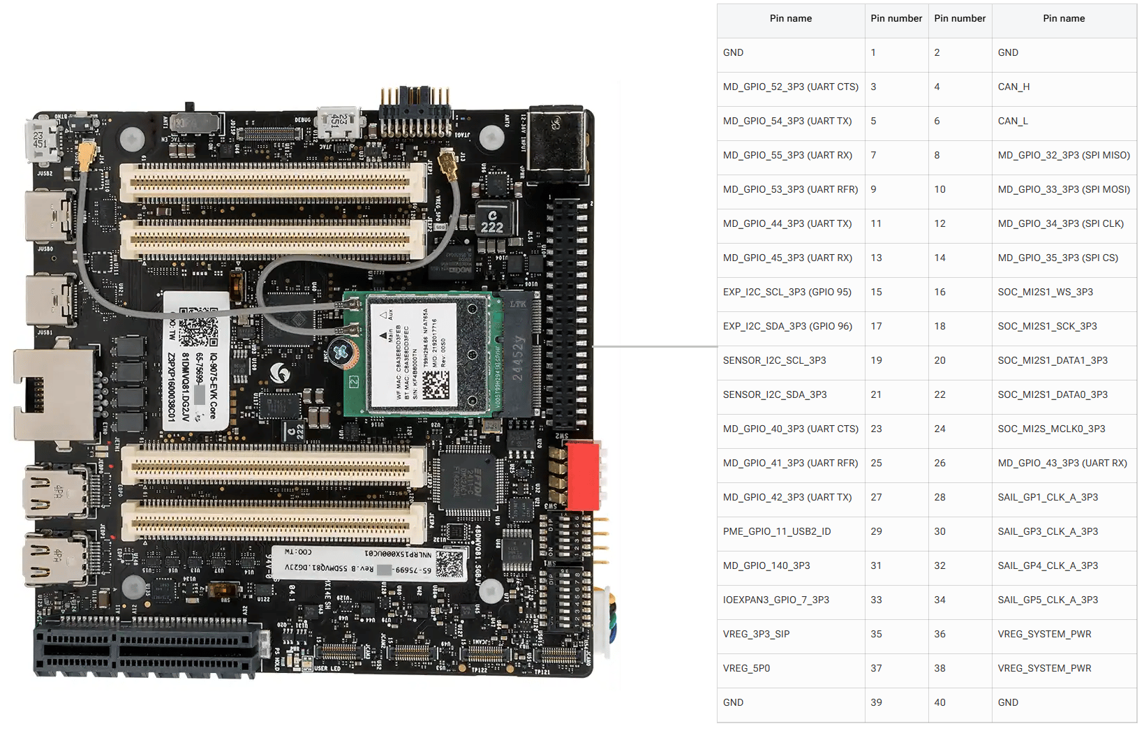
# 40 Pin Low Speed Connector
The Dragonwing IQ8-EVK contains one low-speed connector (JLS1) that provides access to various GPIOs, CAN, QUPs, and other interfaces.
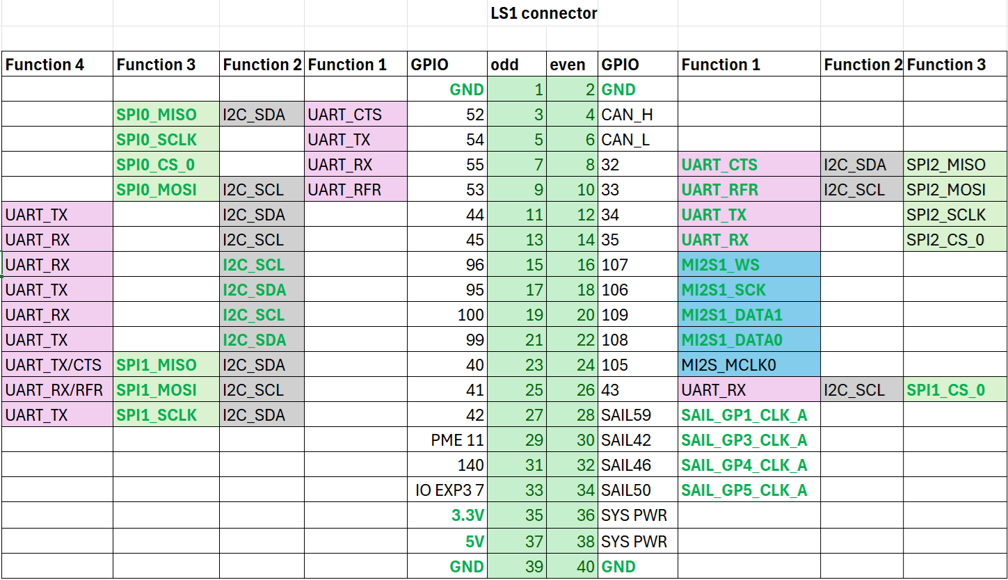
## Pinout
The figure below shows the default functions of the IQ-8275 EVK 40-pin LS connector.
 ## GPIOs
The following commands require root privileges. Use `sudo su` to switch to the root user.
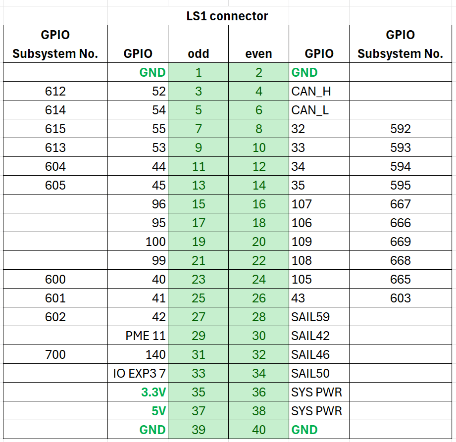
### Identify GPIO Subsystem Numbers
Identify the base GPIO number by running the following command and looking for `platform/f000000.pinctrl` (gpiochip4). For IQ-8275, the base is **560**.
```bash theme={null}
cat /sys/kernel/debug/gpio
```
**Example:** For LS connector Pin 5, GPIO number is 54. The GPIO subsystem number is: 560 + 54 = **614**.
## GPIOs
The following commands require root privileges. Use `sudo su` to switch to the root user.
### Identify GPIO Subsystem Numbers
Identify the base GPIO number by running the following command and looking for `platform/f000000.pinctrl` (gpiochip4). For IQ-8275, the base is **560**.
```bash theme={null}
cat /sys/kernel/debug/gpio
```
**Example:** For LS connector Pin 5, GPIO number is 54. The GPIO subsystem number is: 560 + 54 = **614**.
 ### Control GPIOs via sysfs
```bash theme={null}
cd /sys/class/gpio
echo 614 > export
```
```bash theme={null}
cd gpio614
echo out > direction
echo 1 > value
```
| Attribute | Values |
| ----------- | ----------------------------------- |
| `direction` | `in` (input), `out` (output) |
| `value` | `0` (low), `1` (high) |
| `edge` | `rising`, `falling`, `both`, `none` |
```bash theme={null}
cd ..
echo 614 > unexport
```
### GPIO Code Examples
Sets pin 5 as output, pin 7 as input, and loops to check the level of pin 7.
```bash theme={null}
gcc gpio.c -o gpio
```
Short pin 5 and pin 7 with a Dupont wire.
Pay attention to pin order. Do not short power and ground pins — this may damage the board.
```bash theme={null}
./gpio
```
Install `python3-periphery`:
```bash theme={null}
apt install python3-periphery
```
Short pin 5 and pin 7 with a Dupont wire.
Pay attention to pin order. Do not short power and ground pins — this may damage the board.
```bash theme={null}
python3 gpio.py
```
## UART
Pins 5 and 7 are configured for UART by default (GPIO lines 54 and 55, mapping to `uart12 = qup1_se5 (0xa98000)`).
Follow the [Modify serial engine node](./peripheral_interface_overview#modify-serial-engine-node) procedure to enable the UART interface. After enabling, the device node appears at `/dev/ttyHS3`.
Short pin 5 and pin 7 with a Dupont wire.
Do not short power and ground pins.
```bash theme={null}
sudo stty -F /dev/ttyHS3 ispeed 115200 ospeed 115200
sudo stty -F /dev/ttyHS3 115200 -echo -icanon -isig -iexten -icrnl -ixon -opost
```
**Terminal 1 (RX):** `sudo cat /dev/ttyHS3`
**Terminal 2 (TX):** `echo "hello world!" > /dev/ttyHS3`
## I2C
Pins 8 and 10 are configured for I2C by default (GPIO lines 32 and 33, mapping to `i2c4 = qup0_se4 (0x990000)`).
Follow the [Modify serial engine node](./peripheral_interface_overview#modify-serial-engine-node) procedure to enable the I2C interface.
```bash theme={null}
ls /dev/i2c*
sudo apt install -y i2c-tools
i2cdetect -l
i2cdetect -a -y -r 20
```
## SPI
Pins 11 and 13 are configured for SPI by default (GPIO lines 44 and 45, mapping to `spi10 = qup1_se3 (0xa8c000)`).
Follow the [Modify serial engine node](./peripheral_interface_overview#modify-serial-engine-node) procedure to enable the SPI interface.
```bash theme={null}
sudo apt install python3-spidev
```
### Control GPIOs via sysfs
```bash theme={null}
cd /sys/class/gpio
echo 614 > export
```
```bash theme={null}
cd gpio614
echo out > direction
echo 1 > value
```
| Attribute | Values |
| ----------- | ----------------------------------- |
| `direction` | `in` (input), `out` (output) |
| `value` | `0` (low), `1` (high) |
| `edge` | `rising`, `falling`, `both`, `none` |
```bash theme={null}
cd ..
echo 614 > unexport
```
### GPIO Code Examples
Sets pin 5 as output, pin 7 as input, and loops to check the level of pin 7.
```bash theme={null}
gcc gpio.c -o gpio
```
Short pin 5 and pin 7 with a Dupont wire.
Pay attention to pin order. Do not short power and ground pins — this may damage the board.
```bash theme={null}
./gpio
```
Install `python3-periphery`:
```bash theme={null}
apt install python3-periphery
```
Short pin 5 and pin 7 with a Dupont wire.
Pay attention to pin order. Do not short power and ground pins — this may damage the board.
```bash theme={null}
python3 gpio.py
```
## UART
Pins 5 and 7 are configured for UART by default (GPIO lines 54 and 55, mapping to `uart12 = qup1_se5 (0xa98000)`).
Follow the [Modify serial engine node](./peripheral_interface_overview#modify-serial-engine-node) procedure to enable the UART interface. After enabling, the device node appears at `/dev/ttyHS3`.
Short pin 5 and pin 7 with a Dupont wire.
Do not short power and ground pins.
```bash theme={null}
sudo stty -F /dev/ttyHS3 ispeed 115200 ospeed 115200
sudo stty -F /dev/ttyHS3 115200 -echo -icanon -isig -iexten -icrnl -ixon -opost
```
**Terminal 1 (RX):** `sudo cat /dev/ttyHS3`
**Terminal 2 (TX):** `echo "hello world!" > /dev/ttyHS3`
## I2C
Pins 8 and 10 are configured for I2C by default (GPIO lines 32 and 33, mapping to `i2c4 = qup0_se4 (0x990000)`).
Follow the [Modify serial engine node](./peripheral_interface_overview#modify-serial-engine-node) procedure to enable the I2C interface.
```bash theme={null}
ls /dev/i2c*
sudo apt install -y i2c-tools
i2cdetect -l
i2cdetect -a -y -r 20
```
## SPI
Pins 11 and 13 are configured for SPI by default (GPIO lines 44 and 45, mapping to `spi10 = qup1_se3 (0xa8c000)`).
Follow the [Modify serial engine node](./peripheral_interface_overview#modify-serial-engine-node) procedure to enable the SPI interface.
```bash theme={null}
sudo apt install python3-spidev
```