> ## Documentation Index
> Fetch the complete documentation index at: https://dragonwingdocs.qualcomm.com/llms.txt
> Use this file to discover all available pages before exploring further.

# I2C

export const tdA = {
  border: "1px solid #ddd",
  padding: "10px 14px",
  textAlign: "left",
  verticalAlign: "top"
};
export const thA1 = {
  border: "1px solid #ddd",
  padding: "10px 14px",
  textAlign: "center",
  backgroundColor: "#f5f5f5",
  fontWeight: "600",
  color: "#333",
  width: "20%"
};
export const thA2 = {
  border: "1px solid #ddd",
  padding: "10px 14px",
  textAlign: "center",
  backgroundColor: "#f5f5f5",
  fontWeight: "600",
  color: "#333",
  width: "80%"
};
export const thAeq = {
  border: "1px solid #ddd",
  padding: "10px 14px",
  textAlign: "center",
  backgroundColor: "#f5f5f5",
  fontWeight: "600",
  color: "#333"
};
export const tblA = {
  borderCollapse: "collapse",
  width: "100%",
  fontSize: "14px",
  tableLayout: "fixed"
};

互联集成电路（I2C）是一种双向 2 线总线，是由 Philips 于 20 世纪 80 年代开发的高效 IC 间控制总线。总线上的每个设备都有自己唯一的地址（在由 Philips 牵头的 I2C 管理机构注册）。I2C 核心支持多控制器模式、10 位目标地址和 10 位可扩展地址。有关 I2C 的更多信息，请参阅 [https://www.i2c-bus.org/fileadmin/ftp/i2c\_bus\_specification\_1995.pdf](https://www.i2c-bus.org/fileadmin/ftp/i2c_bus_specification_1995.pdf)。

### **I2C 通信序列概述**

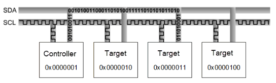
下图显示了 I2C 中控制器与目标设备之间的通信序列。

<Frame>
  <img src="https://mintcdn.com/qualcomm-prod/rpHTx_a6zriKQll9/System/Interfaces/images/I2C_data_fow.png?fit=max&auto=format&n=rpHTx_a6zriKQll9&q=85&s=e015beb887ef057099b693280be45765" alt="I2C 数据流" width="544" height="165" data-path="System/Interfaces/images/I2C_data_fow.png" />
</Frame>

<p align="center"><strong>图：I2C 控制器与目标设备通信序列</strong></p>

例如，任何设备都不能使用 I2C 规范中列出的 1111-0XX，以及时钟频率为 3.4 MHz 的高速模式。

以下是 I2C 模式及支持的速度。

* 标准模式：100 kbps
* 快速模式：400 kbps
* 增强快速模式（Fast mode plus）：1 Mbps

支持的最大带宽为 1 MHz。

### **I2C 数据包格式**

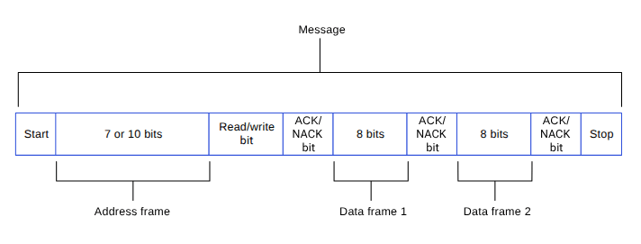
控制器发送 7 位或 10 位地址，如下图所示。除地址外，还会发送 1 位读/写位，指示操作类型。数据以 8 位为单位在 SDA 线上按序传输。每传输一个字节，接收数据的设备都会回发一个 ACK 位（共九个时钟脉冲）。

* ACK 位为低电平：已接收数据并准备好接受下一个字节。
* ACK 位为高电平：已接收数据但无法接受更多数据。控制器随后使用 STOP 序列终止传输。

<Frame>
  <img src="https://mintcdn.com/qualcomm-prod/rpHTx_a6zriKQll9/System/Interfaces/images/I2C_data_packet.png?fit=max&auto=format&n=rpHTx_a6zriKQll9&q=85&s=6ae553baf55358415e2e2b3ecfcbfa1a" alt="I2C 数据包" width="712" height="271" data-path="System/Interfaces/images/I2C_data_packet.png" />
</Frame>

<p align="center"><strong>图：I2C 数据包</strong></p>

### **I2C 时序**

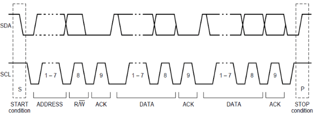
当 SCL 为高电平时，SDA 必须保持稳定，不能变化。只有当时钟线为低电平时，数据线才能变化。但有两个例外：START 和 STOP 序列。

<Frame>
  <img src="https://mintcdn.com/qualcomm-prod/rpHTx_a6zriKQll9/System/Interfaces/images/I2C_sequence.png?fit=max&auto=format&n=rpHTx_a6zriKQll9&q=85&s=62d0229983d9443d8b8f1b3a87b48cff" alt="I2C 时序" width="643" height="238" data-path="System/Interfaces/images/I2C_sequence.png" />
</Frame>

<p align="center"><strong>图：I2C 时序</strong></p>

## **I2C 功能**

本节介绍 I2C 串行引擎传输模式以及每种模式适用的不同场景。下表列出了各 I2C 子系统驱动程序中启用的传输模式。

**表：I2C 传输模式**

<table style={tblA}>
  <thead>
    <tr>
      <th style={thAeq}>子系统</th>
      <th style={thAeq}>传输模式</th>
      <th style={thAeq}>描述</th>
    </tr>
  </thead>

  <tbody>
    <tr>
      <td style={tdA}>Linux</td>

      <td style={tdA}>
        <ul>
          <li>FIFO（低速）</li>
          <li>CPU DMA（高速）</li>
          <li>GSI</li>
        </ul>
      </td>

      <td style={tdA}>
        <ul>
          <li>支持 100 kHz、400 kHz 和 1000 kHz 总线速度</li>
          <li>支持符合 I2C 规范的 7 位目标地址</li>
        </ul>
      </td>
    </tr>

    <tr>
      <td style={tdA}>Boot</td>
      <td style={tdA}>FIFO</td>

      <td style={tdA} />
    </tr>

    <tr>
      <td style={tdA}>aDSP/Qualcomm TEE/SDC</td>
      <td style={tdA}>FIFO</td>

      <td style={tdA} />
    </tr>
  </tbody>
</table>

## **I2C 接口组件**

本节提供有关子系统驱动程序、内核设备树节点及相关文档的信息。

**表：I2C 接口：Linux**

<table style={tblA}>
  <thead>
    <tr>
      <th style={thA1}>文件类型</th>
      <th style={thA2}>描述</th>
    </tr>
  </thead>

  <tbody>
    <tr>
      <td style={tdA}>设备树源</td>

      <td style={tdA}>
        <ul>
          <li>QCS6490 和 QCS5430：[https://git.linaro.org/kernel-org/linux-next.git/tree/arch/arm64/boot/dts/qcom/sc7280.dtsi](https://git.linaro.org/kernel-org/linux-next.git/tree/arch/arm64/boot/dts/qcom/sc7280.dtsi)</li>
          <li>Dragonwing IQ-9075：[https://github.com/torvalds/linux/blob/master/arch/arm64/boot/dts/qcom/sa8775p.dtsi](https://github.com/torvalds/linux/blob/master/arch/arm64/boot/dts/qcom/sa8775p.dtsi)</li>
          <li>Dragonwing IQ-615：[https://git.kernel.org/pub/scm/linux/kernel/git/qcom/linux.git/tree/arch/arm64/boot/dts/qcom/qcs615.dtsi?h=arm64-for-6.16](https://git.kernel.org/pub/scm/linux/kernel/git/qcom/linux.git/tree/arch/arm64/boot/dts/qcom/qcs615.dtsi?h=arm64-for-6.16)</li>
        </ul>
      </td>
    </tr>

    <tr>
      <td style={tdA}>`Pinctrl` 设置</td>

      <td style={tdA}>
        <ul>
          <li>QCS6490 和 QCS5430：[https://git.linaro.org/kernel-org/linux-next.git/tree/arch/arm64/boot/dts/qcom/sc7280.dtsi](https://git.linaro.org/kernel-org/linux-next.git/tree/arch/arm64/boot/dts/qcom/sc7280.dtsi)</li>
          <li>Dragonwing IQ-9075：[https://github.com/torvalds/linux/blob/master/arch/arm64/boot/dts/qcom/sa8775p.dtsi](https://github.com/torvalds/linux/blob/master/arch/arm64/boot/dts/qcom/sa8775p.dtsi)</li>
          <li>Dragonwing IQ-615：[https://git.kernel.org/pub/scm/linux/kernel/git/qcom/linux.git/tree/arch/arm64/boot/dts/qcom/qcs615.dtsi?h=arm64-for-6.16](https://git.kernel.org/pub/scm/linux/kernel/git/qcom/linux.git/tree/arch/arm64/boot/dts/qcom/qcs615.dtsi?h=arm64-for-6.16)</li>
        </ul>
      </td>
    </tr>

    <tr>
      <td style={tdA}>Qualcomm TEE 设置</td>

      <td style={tdA}>
        <ul>
          <li>`/firmware/qualcomm-linux-spf-1-0_ap_standard_oem_nomodem/TZ.XF.5.0/trustzone_images/core/settings/buses/qup_accesscontrol/qupv3/config/<chipset>/QUPAC_Access.c`</li>
        </ul>
      </td>
    </tr>
  </tbody>
</table>

**表：I2C 接口：Boot**

<table style={tblA}>
  <thead>
    <tr>
      <th style={thA1}>文件类型</th>
      <th style={thA2}>描述</th>
    </tr>
  </thead>

  <tbody>
    <tr>
      <td style={tdA}>QUP v3 串行引擎配置</td>

      <td style={tdA}>
        <ul>
          <li>QUP v3 串行引擎：`/firmware/qualcomm-linux-spf-1-0_ap_standard_oem_nomodem/BOOT.MXF.1.0.c1/boot_images/boot/Settings/Soc/<chipset>/Core/Buses/qup_common/<chipset>-qupv3.dtsi`</li>
          <li>GPIO 配置：`/firmware/qualcomm-linux-spf-1-0_ap_standard_oem_nomodem/BOOT.MXF.1.0.c1/boot_images/boot/Settings/Soc/<chipset>/Core/Buses/qup_common/<chipset>-qupv3-pinctrl.dtsi`</li>
        </ul>
      </td>
    </tr>

    <tr>
      <td style={tdA}>Qualcomm TEE 设置</td>

      <td style={tdA}>
        <ul>
          <li>`/firmware/qualcomm-linux-spf-1-0_ap_standard_oem_nomodem/TZ.XF.5.0/trustzone_images/core/settings/buses/qup_accesscontrol/qupv3/config/<chipset>/QUPAC_Access.c`</li>
        </ul>
      </td>
    </tr>
  </tbody>
</table>

**表：I2C 接口：aDSP/SLPI/SDC**

<table style={tblA}>
  <thead>
    <tr>
      <th style={thA1}>文件类型</th>
      <th style={thA2}>描述</th>
    </tr>
  </thead>

  <tbody>
    <tr>
      <td style={tdA}>QUP v3 串行引擎配置</td>

      <td style={tdA}>
        <ul>
          <li>`/firmware/qualcomm-linux-spf-1-0_ap_standard_oem_nomodem/ADSP.HT.5.5.c8/adsp_proc/core/settings/buses/qup_common/config/<chipset>/adsp/ssc/qup_devcfg.c`</li>
          <li>`/firmware/qualcomm-linux-spf-1-0_ap_standard_oem_nomodem/ADSP.HT.5.5.c8/adsp_proc/core/settings/buses/qup_fw/config/<chipset>/fw_devcfg.c`</li>
          <li>`settings/buses/qup_common/config/<chipset>/adsp/ssc/qup_devcfg.json`</li>
        </ul>
      </td>
    </tr>

    <tr>
      <td style={tdA}>固件配置设置</td>

      <td style={tdA}>
        <ul>
          <li>`/firmware/qualcomm-linux-spf-1-0_ap_standard_oem_nomodem/ADSP.HT.5.5.c8/adsp_proc/core/settings/buses/qup_fw/config/<chipset>/fw_devcfg.c`</li>
          <li>`/firmware/qualcomm-linux-spf-1-0_ap_standard_oem_nomodem/ADSP.HT.5.5.c8/adsp_proc/core/settings/buses/qup_fw/config/<chipset>/fw_devcfg.xml`</li>
        </ul>
      </td>
    </tr>
  </tbody>
</table>

**表：I2C 接口：Qualcomm TEE**

<table style={tblA}>
  <thead>
    <tr>
      <th style={thA1}>文件类型</th>
      <th style={thA2}>描述</th>
    </tr>
  </thead>

  <tbody>
    <tr>
      <td style={tdA}>QUP v3 串行引擎配置</td>

      <td style={tdA}>
        <ul>
          <li>`/firmware/qualcomm-linux-spf-1-0_ap_standard_oem_nomodem/TZ.XF.5.0/trustzone_images/core/settings/buses/i2c/qupv3/config/<chipset>/tz/i2c_devcfg_user.h`</li>
          <li>`/firmware/qualcomm-linux-spf-1-0_ap_standard_oem_nomodem/TZ.XF.5.0/trustzone_images/core/settings/buses/i2c/qupv3/config/<chipset>/tz/i2c_devcfg_user.c`</li>
          <li>`/firmware/qualcomm-linux-spf-1-0_ap_standard_oem_nomodem/TZ.XF.5.0/trustzone_images/core/settings/buses/i2c/qupv3/config/<chipset>/tz/i2c_devcfg.xml`</li>
        </ul>
      </td>
    </tr>

    <tr>
      <td style={tdA}>Qualcomm TEE 设置</td>

      <td style={tdA}>
        <ul>
          <li>`/firmware/qualcomm-linux-spf-1-0_ap_standard_oem_nomodem/TZ.XF.5.0/trustzone_images/core/settings/buses/qup_accesscontrol/qupv3/config/<chipset>/QUPAC_Access.c`</li>
        </ul>
      </td>
    </tr>
  </tbody>
</table>

### **I2C API**

本节列出了以下子系统的 I2C API。

* Linux：
  * [https://github.com/torvalds/linux/blob/master/include/linux/i2c.h](https://github.com/torvalds/linux/blob/master/include/linux/i2c.h)。
  * [https://github.com/torvalds/linux/blob/master/include/linux/i2c-dev.h](https://github.com/torvalds/linux/blob/master/include/linux/i2c-dev.h)。
* Boot：boot\_images/boot/QcomPkg/Include/i2c\_api.h
* aDSP/SDC/SLPI：adsp\_proc/core/api/buses/i2c\_api.h
* Qualcomm TEE：trustzone\_images/core/buses/api/i2c/qupv3/i2c\_api.h

## **I2C 软件设备树配置**

本节提供有关 I2C 设备树配置的信息以及设备节点的文档。

### **Linux**

有关配置设置文件，请参阅以下 DTSI 文件。

* QCS6490 和 QCS5430：[https://git.linaro.org/kernel-org/linux-next.git/tree/arch/arm64/boot/dts/qcom/sc7280.dtsi](https://git.linaro.org/kernel-org/linux-next.git/tree/arch/arm64/boot/dts/qcom/sc7280.dtsi)
* Dragonwing IQ-9075：[https://github.com/torvalds/linux/blob/master/arch/arm64/boot/dts/qcom/sa8775p.dtsi](https://github.com/torvalds/linux/blob/master/arch/arm64/boot/dts/qcom/sa8775p.dtsi)
* Dragonwing IQ-615：[https://git.kernel.org/pub/scm/linux/kernel/git/qcom/linux.git/tree/arch/arm64/boot/dts/qcom/qcs615.dtsi?h=arm64-for-6.16](https://git.kernel.org/pub/scm/linux/kernel/git/qcom/linux.git/tree/arch/arm64/boot/dts/qcom/qcs615.dtsi?h=arm64-for-6.16)

有关更多详细信息，请参阅 [https://github.com/torvalds/linux/blob/master/Documentation/devicetree/bindings/i2c/qcom%2Ci2c-geni-qcom.yaml](https://github.com/torvalds/linux/blob/master/Documentation/devicetree/bindings/i2c/qcom%2Ci2c-geni-qcom.yaml) 中的 `i2c-geni-qcom.yaml` 文件，以及 [https://github.com/torvalds/linux/blob/master/drivers/i2c/busses/i2c-qcom-geni.c](https://github.com/torvalds/linux/blob/master/drivers/i2c/busses/i2c-qcom-geni.c) 文件中的 I2C 驱动程序。

```text theme={null}
i2c1: i2c@984000 {
compatible = "qcom,geni-i2c";
reg = <0 0x00984000 0 0x4000>;
clocks = <&gcc GCC_QUPV3_WRAP0_S1_CLK>;
clock-names = "se";
pinctrl-names = "default";
pinctrl-0 = <&qup_i2c1_data_clk>;
interrupts = <GIC_SPI 602 IRQ_TYPE_LEVEL_HIGH>;
#address-cells = <1>;
#size-cells = <0>;
interconnects = <&clk_virt MASTER_QUP_CORE_0 0 &clk_virt SLAVE_QUP_CORE_0 0>,
		<&gem_noc MASTER_APPSS_PROC 0 &cnoc2 SLAVE_QUP_0 0>,
		<&aggre1_noc MASTER_QUP_0 0 &mc_virt SLAVE_EBI1 0>;
interconnect-names = "qup-core", "qup-config",
		"qup-memory";
power-domains = <&rpmhpd SC7280_CX>;
required-opps = <&rpmhpd_opp_low_svs>;
	        dmas = <&gpi_dma0 0 1 QCOM_GPI_I2C>,
		 <&gpi_dma0 1 1 QCOM_GPI_I2C>;
dma-names = "tx", "rx";
status = "disabled";
			};
```

有关 GPIO `pinctrl` 配置的内核文档，请参阅以下文件。

* QCS6490 和 QCS5430：[https://git.linaro.org/kernel-org/linux-next.git/tree/arch/arm64/boot/dts/qcom/sc7280.dtsi](https://git.linaro.org/kernel-org/linux-next.git/tree/arch/arm64/boot/dts/qcom/sc7280.dtsi)
* Dragonwing IQ-9075：[https://github.com/torvalds/linux/blob/master/arch/arm64/boot/dts/qcom/sa8775p.dtsi](https://github.com/torvalds/linux/blob/master/arch/arm64/boot/dts/qcom/sa8775p.dtsi)
* Dragonwing IQ-615：[https://git.kernel.org/pub/scm/linux/kernel/git/qcom/linux.git/tree/arch/arm64/boot/dts/qcom/qcs615.dtsi?h=arm64-for-6.16](https://git.kernel.org/pub/scm/linux/kernel/git/qcom/linux.git/tree/arch/arm64/boot/dts/qcom/qcs615.dtsi?h=arm64-for-6.16)
* `Documentation/devicetree/bindings/pinctrl/qcom,<chipset>-tlmm.yaml`

QUP v3 串行引擎 GPIO 的相应配置存在于 `pinctrl.dtsi` 文件中并已完成映射。

```text theme={null}
qup_i2c1_data_clk: qup-i2c1-data-clk-state {
				pins = "gpio4", "gpio5";
				function = "qup01";
			};
```

在 `QUPAC_Access.c` 文件中，确保指定协议的特定串行引擎配置是针对 I2C 协议的。Qualcomm TEE 构建：

```text theme={null}
/firmware/qualcomm-linux-spf-1-0_ap_standard_oem_nomodem/TZ.XF.5.0/trustzone_images/core/settings/buses/qup_accesscontrol/qupv3/config/<chipset>/QUPAC_Access.c
```

修改所需设置，或参考为 QUP v3 串行引擎实例分配的默认设置。以下示例配置在 I2C 中默认启用。

```text theme={null}
/*   PeriphID,         ProtocolID,               Mode,  NsOwner,       bAllowFifo, bLoad, bModExcl  */
  { QUPV3_0_SE0, QUPV3_PROTOCOL_I2C,     QUPV3_MODE_FIFO, AC_HLOS,            TRUE,  TRUE,  FALSE }, // LT9611 and QPS615 I2C
  { QUPV3_0_SE1, QUPV3_PROTOCOL_I2C,     QUPV3_MODE_FIFO, AC_HLOS,            TRUE,  TRUE,  FALSE }, // APPS I2C - PCIE/ USB Type C
  { QUPV3_0_SE2, QUPV3_PROTOCOL_I2C,     QUPV3_MODE_FIFO, AC_HLOS,            TRUE,  TRUE,  FALSE }, // SMB / LS1 I2C

{ QUPV3_1_SE1, QUPV3_PROTOCOL_I2C,     QUPV3_MODE_FIFO, AC_HLOS,            TRUE,  TRUE,  FALSE }, // NFC I2C
 { QUPV3_1_SE2, QUPV3_PROTOCOL_I2C,     QUPV3_MODE_FIFO, AC_HLOS,            TRUE,  TRUE,  FALSE }, // HDMI OUT for
 { QUPV3_1_SE5, QUPV3_PROTOCOL_I2C,     QUPV3_MODE_GSI,  AC_HLOS,            FALSE, TRUE,  FALSE}, // Legacy Touch
```

### **Boot**

1. 在 UEFI 中配置 I2C。可从以下位置访问配置文件。
   * QUP v3 串行引擎：`/firmware/qualcomm-linux-spf-1-0_ap_standard_oem_nomodem/BOOT.MXF.1.0.c1/boot_images/boot/Settings/Soc/<chipset>/Core/Buses/qup_common/<chipset>-qupv3.dtsi`
   * Qualcomm TEE 设置：`/firmware/qualcomm-linux-spf-1-0_ap_standard_oem_nomodem/TZ.XF.5.0/trustzone_images/core/settings/buses/qup_accesscontrol/qupv3/config/<chipset>/QUPAC_Access.c`

<Note>
  注意：有关 boot 中的配置设置，请参阅 [Boot](https://dragonwingdocs.qualcomm.com/System/Interfaces/spi#boot)。
</Note>

2. 在 UEFI 的 `/QcomPkg/SocPkg/<chipset>/LAA/Core.fdf` 中启用 I2C 协议。
   ```text theme={null}
   -#INF QcomPkg/Drivers/I2CDxe/I2CDxe.inf 
   +INF QcomPkg/Drivers/I2CDxe/I2CDxe.inf
   ```
3. 应用程序启用 I2C 接口。然后，应用程序通过 I2C 接口执行读写操作。有关 I2C 函数用法的信息，请参阅 `boot_images/QcomPkg/QcomTestPkg/I2CApp/I2Ceeprom.c`。
4. 在代码中按顺序添加 `i2c_open->i2c_read/i2c_write->i2c_close`。
5. 在调用 `I2c_open` 之前，通过验证设备/UEFI 启动日志，确保 `GpiDxe.inf` 和 `I2C.efi` 文件已加载。

### **aDSP/SDC**

在 aDSP 子系统的启动序列期间，会随 SSC QUP 执行固件加载。配置文件位于 aDSP 构建中的以下位置：

```text theme={null}
/firmware/qualcomm-linux-spf-1-0_ap_standard_oem_nomodem/ADSP.HT.5.5.c8/adsp_proc/core/settings/buses/qup_fw/config/<chipset>/fw_devcfg.c
/firmware/qualcomm-linux-spf-1-0_ap_standard_oem_nomodem/ADSP.HT.5.5.c8/adsp_proc/core/settings/buses/qup_fw/config/<chipset>/fw_devcfg.xml
```

以下配置是加载 I2C 固件的 SSC QUP SE1、SE2 和 SE3 设置的示例。

```text theme={null}
se_cfg se1_cfg = { 0x84000, SE_PROTOCOL_I2C,    GSI,     TRUE, TRUE  };
se_cfg se2_cfg = { 0x88000, SE_PROTOCOL_I2C,    GSI,     TRUE, TRUE  };
se_cfg se3_cfg = { 0x8C000, SE_PROTOCOL_I2C,    GSI,     FALSE, TRUE  };
```

**GPIO 配置**：QUP v3 通用驱动程序中的每个串行引擎都配置了默认 GPIO 配置。QUP v3 通用驱动程序根据串行引擎中加载的协议获取 GPIO 配置。文件路径：

```text theme={null}
/firmware/qualcomm-linux-spf-1-0_ap_standard_oem_nomodem/ADSP.HT.5.5.c8/adsp_proc/core/settings/buses/qup_common/config/<chipset>/adsp/ssc/qup_instance_mapping.c
```

默认 GPIO 配置可按如下方式覆盖。

```text theme={null}
{      .instance_id          =  5 ,         //Instance ID
        .qup              =  QUP_SSC,    //QUP Type
        .se_index         =  4,          //SE ID
        .se_data          =  NULL,       //devcfg_map
        .protocol_io_cfg  =  {
                                TLMM_MAP(TLMM_GPIO_KEEPER ,TLMM_GPIO_2MA,TLMM_GPIO_KEEPER ),              //SLEEP CFG
                                TLMM_MAP(TLMM_GPIO_NO_PULL,TLMM_GPIO_6MA,TLMM_GPIO_KEEPER ),              //SPI CFG
                                TLMM_MAP(TLMM_GPIO_NO_PULL,TLMM_GPIO_2MA,TLMM_GPIO_NO_PULL),              //UART CFG
                                TLMM_MAP(TLMM_GPIO_PULL_UP,TLMM_GPIO_2MA,TLMM_GPIO_NO_PULL),              //I2C CFG
                                TLMM_MAP(TLMM_GPIO_PULL_UP,TLMM_GPIO_2MA,TLMM_GPIO_KEEPER )               //I3C CFG
                             },
        .se_exclusive     =  TRUE,
}
```

TLMM\_MAP 是用于初始化活动和睡眠状态 GPIO 配置的宏。例如，TLMM\_MAP 宏的示例用法。

```text theme={null}
TLMM_MAP (active state pull type, drive strength, sleep state pull type)
```

### **Qualcomm TEE**

用于 I2C 的 QUP v3 串行引擎可按如下方式配置。文件路径：

```text theme={null}
settings/buses/i2c/qupv3/config/<chipset>/tz/i2c_devcfg_user.h
```

```text theme={null}
#define ENABLE_I2C_08
```

`ENABLE_I2C_<num>` 中的编号基于串行引擎的序号（从 0 开始）。例如，如果有两个 QUP：QUPV3\_0 有七个串行引擎，QUPV3\_1 有八个串行引擎，则用户必须启用 QUPV3\_2\_SE2。该宏应为 `ENABLE_I2C_08`。

GPIO 配置：驱动强度和上拉/下拉按引脚配置，SDA 位于索引 0，SCL 位于索引 1。文件路径：

```text theme={null}
settings/buses/i2c/qupv3/config/<chipset>/tz/i2c_devcfg_user.c
```

```text theme={null}
i2c_plat_device_config_user i2c_device_user_config_0 =
{
    {0,0},        //.drive_strength index: 0 - SDA, 1 - SCL
                                    value: 0 - 2MA, 1 - 4MA, 2 - 6MA
    {3,3},       //.pull  index: 0 - SDA, 1 - SCL
                       value: 0 - NO_PULL, 1 = PULL_DOWN, 2 = KEEPER, 3 = PULL_UP
    0xFF,        //.gpii_idx 
    0,           //.mode_select  not supported for TZ
    0,           //.flags not supported for TZ
};
```

QUPAC 访问控制：来自 Qualcomm TEE 子系统的固件加载和访问控制权限在以下 QUPAC 访问文件中配置：

```text theme={null}
/firmware/qualcomm-linux-spf-1-0_ap_standard_oem_nomodem/TZ.XF.5.0/trustzone_images/core/settings/buses/qup_accesscontrol/qupv3/config/<chipset>/QUPAC_Access.c
```

## **配置 I2C 接口**

本节提供有关 I2C 软件驱动程序内核配置和设备树节点更改的信息。

### **Linux**

支持 I2C 接口需要以下驱动程序内核配置。

* 驱动程序源代码：[https://github.com/torvalds/linux/blob/master/drivers/i2c/busses/i2c-qcom-geni.c](https://github.com/torvalds/linux/blob/master/drivers/i2c/busses/i2c-qcom-geni.c)
* 内核 `defconfig` 文件路径：

  ```text theme={null}
  <workspace_path_of_LINUX_kernel_image>/sources/kernel/kernel_platform/kernel/arch/arm64/configs/qcom_defconfig
  ```

需要启用以下内核配置。

* `CONFIG_QCOM_GENI_SE=y`
* `CONFIG_I2C_CHARDEV=m`
* `CONFIG_I2C_QCOM_GENI=m` 用于配置用户空间应用程序
* `CONFIG_QCOM_GPI_DMA=m` 用于启用 GSI 支持

要启用 I2C DT 节点进行验证，请将以下补丁应用于 `/arch/arm64/boot/dts/qcom/<chipset>.dtsi` 文件。

```text theme={null}
diff --git a/arch/arm64/boot/dts/qcom/<chipset>.dtsi b/arch/arm64/boot/dts/qcom/<chipset>.dtsi
index 8575f0b..cced7c0 100644
--- a/arch/arm64/boot/dts/qcom/<chipset>.dtsi
+++ b/arch/arm64/boot/dts/qcom/<chipset>.dtsi
@@ -6865,3 +6865,7 @@
 <GIC_PPI 10 IRQ_TYPE_LEVEL_LOW>;
 };
 };
+
+ &i2c1 {
+ status = "ok";
+};
```

<Note>
  注意：您应编译内核配置和设备树更改。编译后，可以将镜像加载到设备上以验证接口。有关接口验证的信息，请参阅[验证 I2C 接口](https://dragonwingdocs.qualcomm.com/System/Interfaces/i2-c#verify-i2c-interface)部分。
</Note>

## **验证 I2C 接口**

本节介绍 I2C 驱动程序和 Qualcomm 驱动程序的验证过程和测试结果。

### **Linux**

有关上游 I2C 内核测试应用程序，请参阅 [https://cdn.kernel.org/pub/software/utils/i2c-tools/i2c-tools-4.3.tar.gz](https://cdn.kernel.org/pub/software/utils/i2c-tools/i2c-tools-4.3.tar.gz)。

要交叉编译工具，请执行以下操作。

1. 从 [https://cdn.kernel.org/pub/software/utils/i2c-tools/i2c-tools-4.3.tar.gz](https://cdn.kernel.org/pub/software/utils/i2c-tools/i2c-tools-4.3.tar.gz) 下载 `i2c-tool`。
2. 从下载的 `tar` 文件中解压该工具。
   ```text theme={null}
   tar -xzvf <i2c-tool-path>
   ```
3. 将当前目录切换到 `i2c-tool` 路径。
   ```text theme={null}
   cd <i2c-tool-path>
   ```
4. 安装该工具。
   ```text theme={null}
   sudo apt-get install gcc-aarch64-linux-gnu
   ```
5. 设置交叉编译环境。
   ```text theme={null}
   export CC=aarch64-linux-gnu-gcc
   ```
6. 编译该工具。
   ```text theme={null}
   make USE_STATIC_LIB=1
   ```
   二进制文件生成在 `<i2c-tool-path>/tools/` 中。

通过在 SSH shell 中检查 `dev` 节点（`/dev/i2c-0` 和 `/dev/i2c-1`）来验证驱动程序，或使用 ADB shell。有关如何运行 SSH 的更多信息，请参阅[使用 SSH](https://docs.qualcomm.com/bundle/publicresource/topics/80-80021-254/how_to.html) 部分。

**验证 I2C 驱动程序**

1. 要验证 I2C 驱动程序，请执行以下操作：
   1. 在 permissive 模式下打开 SSH shell，或使用 ADB shell。
   2. 挂载文件系统。
      ```text theme={null}
      mount -o remount,rw /usr
      ```
   3. 使用 SCP 或类似工具传输文件。
      例如，`scp i2cdetect root@10.92.162.185:/bin`
   4. 分配执行权限。
      ```text theme={null}
      chmod 777 i2cdetect
      ```
2. 使用 `i2cdetect` 工具验证 I2C 设备。例如，`./i2cdetect -y -r <i2c_instance_num>`。
   ```text theme={null}
   /lib # ./i2cdetect -y -r 0
   ```
   将显示以下输出。
   ```text theme={null}
   0  1  2  3  4  5  6  7  8  9  a  b  c  d  e  f
   00: -- -- -- -- -- -- -- --
   10: -- -- -- -- -- -- -- -- -- -- -- -- -- -- -- --
   20: -- -- -- -- -- -- -- -- -- -- -- 2b -- -- -- --
   30: -- -- -- -- -- -- -- -- -- -- -- -- -- -- -- --
   40: -- -- -- -- 44 -- -- -- -- -- -- -- -- -- -- --
   50: -- -- -- -- -- -- -- -- -- -- -- -- -- -- -- --
   60: -- -- -- -- -- -- -- -- -- -- -- -- -- -- -- --
   70: -- -- -- -- -- -- -- --
   /lib # exit
   ```

**查看 I2C detect 帮助**

有关 I2C 检测及其使用方法的更多信息，请运行以下命令。

```text theme={null}
/lib # ./i2cdetect --help
```

将显示以下输出。

```text theme={null}
Error: Unsupported option "--help"!
Usage: i2cdetect [-y] [-a] [-q|-r] I2CBUS [FIRST LAST]
i2cdetect -F I2CBUS
i2cdetect -l
I2CBUS is an integer or an I2C bus name
If provided, FIRST and LAST limit of the probing range.
```

**识别 DUT 中已探测的设备**

要识别从 DUT 探测到的设备，请运行以下命令。

```text theme={null}
/lib # ./i2cdump -r 0-0xff 0 0x2b b
```

输出：

```text theme={null}
WARNING! This program can confuse your I2C bus, cause data loss and worse!
will probe file /dev/i2c-0, address 0x2b, mode byte
Probe range limited to 0x00-0xff.
Continue? [Y/n] Y
0  1  2  3  4  5  6  7  8  9  a  b  c  d  e  f    0123456789abcdef
00: 00 00 00 00 00 00 00 00 00 00 00 00 00 00 00 00    ................
10: 00 00 00 00 00 00 00 00 00 00 00 00 00 00 00 00    ................
20: 00 00 00 00 00 00 00 00 00 00 00 00 00 00 00 00    ................
30: 00 00 00 00 00 00 00 00 00 00 00 00 00 00 00 00    ................
40: 00 00 00 00 00 00 00 00 00 00 00 00 00 00 00 00    ................
50: 00 00 00 00 00 00 00 00 00 00 00 00 00 00 00 00    ................
60: 00 00 00 00 00 00 00 00 00 00 00 00 00 00 00 00    ................
70: 00 00 00 00 00 00 00 00 00 00 00 00 00 00 00 00    ................
80: 00 00 00 00 00 00 00 00 00 00 00 00 00 00 00 00    ................
90: 00 00 00 00 00 00 00 00 00 00 00 00 00 00 00 00    ................
a0: 00 00 00 00 00 00 00 00 00 00 00 00 00 00 00 00    ................
b0: 00 00 00 00 00 00 00 00 00 00 00 00 00 00 00 00    ................
c0: 00 00 00 00 00 00 00 00 00 00 00 00 00 00 00 00    ................
d0: 00 00 00 00 00 00 00 00 00 00 00 00 00 00 00 00    ................
e0: 00 00 00 00 00 00 00 00 00 00 00 00 00 00 00 00    ................
f0: 00 00 00 00 00 00 00 00 00 00 00 00 00 00 00 00    ................
```

**从设备读取 I2C 数据**

要从设备读取 I2C 数据，请运行以下命令。

```text theme={null}
/lib # ./i2cget 0 0x2b 4 b
```

输出：

```text theme={null}
WARNING! This program can confuse your I2C bus, cause data loss and worse!
Will read from device file /dev/i2c-0, chip address 0x2b, data address
0x04, using read byte data.
Continue? [Y/n] Y
0x00
```

## **调试 I2C 问题**

本节介绍 I2C 软件驱动程序的默认日志记录方法，以启用 I2C 传输失败的日志记录。

### **Linux**

I2C 驱动程序日志通过内核动态调试方法启用。在以下文件中启用 `CONFIG_DYNAMIC_DEBUG` 以支持内核驱动程序的动态调试。

```text theme={null}
<workspace_path_of_LINUX_kernel_image>/sources/kernel/kernel_platform/kernel/arch/arm64/configs/qcom_defconfig
```

要在内核日志（`dmesg`）中启用并查看 I2C 驱动程序日志，请运行以下命令。

```text theme={null}
mount -t debugfs none /sys/kernel/debug
echo -n "file i2c-qcom-geni.c +p" > /sys/kernel/debug/dynamic_debug/control
echo -n "file i2c-core-base.c +p" > /sys/kernel/debug/dynamic_debug/control
echo -n "file i2c-dev.c +p" > /sys/kernel/debug/dynamic_debug/control
echo -n "file i2c-mux.c +p" > /sys/kernel/debug/dynamic_debug/control
echo -n "file gpi.c +p" > /sys/kernel/debug/dynamic_debug/control
```

要调试驱动程序协议加载失败的错误消息 `[ 8.583248] geni_i2c a94000.i2c: Invalid proto 1`，请执行以下操作。

1. 识别板类型。
   示例：QUPV3\_1\_SE5 板类型详细信息
   ```text theme={null}
   B -    461251 - CDT Version:3,Platform ID:34,Major ID:1,Minor ID:0,Subtype:2
   ```
2. 从内核日志中，在以下位置找到平台 ID 和子类型相关的详细信息：
   ```text theme={null}
   /firmware/qualcomm-linux-spf-1-0_ap_standard_oem_nomodem/TZ.XF.5.0/trustzone_images/core/settings/buses/qup_accesscontrol/qupv3/config/<chipset>/QUPAC_Access.xml
   ```
3. 获取 Qualcomm TEE `QUPAC_Access.c` 文件配置。
4. 识别特定于该串行引擎的配置。
5. 在 `QUPAC_Access.xml` 文件中找到平台 ID 类型。
6. 将此平台 ID 类型映射到 `QUPAC_Access.c` 文件中相应的 `qupv3_perms` 结构。
7. 验证 `QUPAC_Access.c` 文件中的协议和模式配置。

## **I2C 示例**

有关上游设备树参考的信息，请参阅以下 DTSI 文件。

* QCS6490 和 QCS5430：[https://git.linaro.org/kernel-org/linux-next.git/tree/arch/arm64/boot/dts/qcom/sc7280.dtsi](https://git.linaro.org/kernel-org/linux-next.git/tree/arch/arm64/boot/dts/qcom/sc7280.dtsi)
* Dragonwing IQ-9075：[https://github.com/torvalds/linux/blob/master/arch/arm64/boot/dts/qcom/sa8775p.dtsi](https://github.com/torvalds/linux/blob/master/arch/arm64/boot/dts/qcom/sa8775p.dtsi)
* Dragonwing IQ-615：[https://git.kernel.org/pub/scm/linux/kernel/git/qcom/linux.git/tree/arch/arm64/boot/dts/qcom/qcs615.dtsi?h=arm64-for-6.16](https://git.kernel.org/pub/scm/linux/kernel/git/qcom/linux.git/tree/arch/arm64/boot/dts/qcom/qcs615.dtsi?h=arm64-for-6.16)

有关 Qualcomm Linux 硬件 SoC 的设备树节点的信息，请参阅以下 DTSI 文件。

* QCS6490 和 QCS5430：[https://git.linaro.org/kernel-org/linux-next.git/tree/arch/arm64/boot/dts/qcom/qcs6490-rb3gen2.dts](https://git.linaro.org/kernel-org/linux-next.git/tree/arch/arm64/boot/dts/qcom/qcs6490-rb3gen2.dts)
* Dragonwing IQ-9075：[https://github.com/torvalds/linux/blob/master/arch/arm64/boot/dts/qcom/sa8775p.dtsi](https://github.com/torvalds/linux/blob/master/arch/arm64/boot/dts/qcom/sa8775p.dtsi)
* Dragonwing IQ-615：[https://git.kernel.org/pub/scm/linux/kernel/git/qcom/linux.git/tree/arch/arm64/boot/dts/qcom/qcs615.dtsi?h=arm64-for-6.16](https://git.kernel.org/pub/scm/linux/kernel/git/qcom/linux.git/tree/arch/arm64/boot/dts/qcom/qcs615.dtsi?h=arm64-for-6.16)