> ## Documentation Index
> Fetch the complete documentation index at: https://dragonwingdocs.qualcomm.com/llms.txt
> Use this file to discover all available pages before exploring further.

# SPI

export const tdA = {
  border: "1px solid #ddd",
  padding: "10px 14px",
  textAlign: "left",
  verticalAlign: "top"
};
export const tdAc = {
  border: "1px solid #ddd",
  padding: "10px 14px",
  textAlign: "center",
  verticalAlign: "middle"
};
export const tdAcBold = {
  border: "1px solid #ddd",
  padding: "10px 14px",
  textAlign: "center",
  verticalAlign: "middle",
  fontWeight: "bold"
};
export const thA1 = {
  border: "1px solid #ddd",
  padding: "10px 14px",
  textAlign: "center",
  backgroundColor: "#f5f5f5",
  fontWeight: "600",
  color: "#333",
  width: "20%"
};
export const thA2 = {
  border: "1px solid #ddd",
  padding: "10px 14px",
  textAlign: "center",
  backgroundColor: "#f5f5f5",
  fontWeight: "600",
  color: "#333",
  width: "80%"
};
export const thAeq = {
  border: "1px solid #ddd",
  padding: "10px 14px",
  textAlign: "center",
  backgroundColor: "#f5f5f5",
  fontWeight: "600",
  color: "#333"
};
export const tblA = {
  borderCollapse: "collapse",
  width: "100%",
  fontSize: "14px",
  tableLayout: "fixed"
};

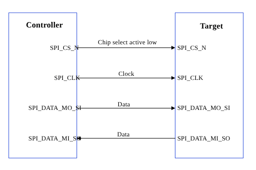
串行外设接口（SPI）是一种以全双工模式工作的同步串行数据链路。SPI 也被称为 4 线串行总线。

<Frame>
  <img src="https://mintcdn.com/qualcomm-prod/rpHTx_a6zriKQll9/System/Interfaces/images/SPI_data_flow.png?fit=max&auto=format&n=rpHTx_a6zriKQll9&q=85&s=bf50308f81f4e720a366cf4b4243c172" alt="SPI 数据流" width="502" height="334" data-path="System/Interfaces/images/SPI_data_flow.png" />
</Frame>

<p align="center"><strong>图：SPI 数据流</strong></p>

SPI 核心支持双向 SPI 标准、点对点以及控制器-目标（controller-target）协议。SPI 核心使用四条片选线（SPI\_CS#\_N）来选择要通信的目标设备。以下两条数据线支持双向数据传输。

* SPI\_DATA\_MO\_SI：控制器数据输出，目标数据输入。
* SPI\_DATA\_MI\_SO：控制器数据输入，目标数据输出。

**表：**

**SPI 中的数据和控制信号**

<table style={tblA}>
  <tbody>
    <tr>
      <td rowSpan="2" style={tdA}>数据信号</td>
      <td style={tdA}>MOSI：控制器数据输出，目标数据输入。</td>
    </tr>

    <tr>
      <td style={tdA}>MISO：控制器数据输入，目标数据输出。</td>
    </tr>

    <tr>
      <td rowSpan="2" style={tdA}>控制信号</td>
      <td style={tdA}>SCLK：由控制器生成并输入到所有目标的时钟。</td>
    </tr>

    <tr>
      <td style={tdA}>CS：片选，当控制器置位其 CS\_N 信号时，对应目标被选中。</td>
    </tr>
  </tbody>
</table>

## **SPI 特性**

本节说明 SPI 串行引擎的传输模式以及各模式适用的不同场景。本节还介绍在各子系统 SPI 驱动中启用的 FIFO 和 DMA。

**表：**

**SPI 传输模式**

<table style={tblA}>
  <thead>
    <tr>
      <th style={thAeq}>子系统</th>
      <th style={thAeq}>传输模式</th>
      <th style={thAeq}>说明</th>
    </tr>
  </thead>

  <tbody>
    <tr>
      <td style={tdA}>Linux</td>

      <td style={tdA}>
        <ul>
          <li>FIFO（低速）</li>
          <li>CPU DMA（高速）</li>
          <li>GSI</li>
        </ul>
      </td>

      <td style={tdA}>支持的最大配置速率为 50 MHz。</td>
    </tr>

    <tr>
      <td style={tdA}>Boot</td>
      <td style={tdA}>FIFO</td>

      <td style={tdA}>
        <ul>
          <li>传输速率最高 50 MHz。主机会将 SPI 时钟频率设置为最接近请求频率的值。</li>
          <li>每个传输字 4 位到 32 位。</li>
          <li>每条总线最多 4 个片选（CS）。</li>
          <li>Boot 阶段不支持 GSI 模式。</li>
          <li>驱动以轮询模式运行。</li>
        </ul>
      </td>
    </tr>

    <tr>
      <td style={tdA}>aDSP</td>

      <td style={tdA}>
        <ul>
          <li>全双工</li>
          <li>半双工</li>
          <li>同步</li>
          <li>串行通信</li>
        </ul>
      </td>

      <td style={tdA}>
        <ul>
          <li>没有显式的通信帧、错误校验或定义的数据字长。</li>
          <li>通信严格在原始位级别进行。</li>
          <li>传输速率最高 50 MHz。主机会将 SPI 时钟频率设置为最接近请求频率的值。</li>
          <li>每个传输字 4 位到 32 位。</li>
          <li>每条总线最多 4 个片选（CS）。</li>
        </ul>
      </td>
    </tr>
  </tbody>
</table>

## **SPI 接口组件**

本节介绍子系统驱动、内核设备树节点及相关文档。

**表：**

**SPI 接口：Linux**

<table style={tblA}>
  <thead>
    <tr>
      <th style={thA1}>文件类型</th>
      <th style={thA2}>说明</th>
    </tr>
  </thead>

  <tbody>
    <tr>
      <td style={tdA}>设备树源文件</td>

      <td style={tdA}>
        <ul>
          <li>QCS6490 和 QCS5430: [https://git.linaro.org/kernel-org/linux-next.git/tree/arch/arm64/boot/dts/qcom/sc7280.dtsi](https://git.linaro.org/kernel-org/linux-next.git/tree/arch/arm64/boot/dts/qcom/sc7280.dtsi)</li>
          <li>Dragonwing IQ-9075: [https://github.com/torvalds/linux/blob/master/arch/arm64/boot/dts/qcom/sa8775p.dtsi](https://github.com/torvalds/linux/blob/master/arch/arm64/boot/dts/qcom/sa8775p.dtsi)</li>
          <li>Dragonwing IQ-615: [https://git.kernel.org/pub/scm/linux/kernel/git/qcom/linux.git/tree/arch/arm64/boot/dts/qcom/qcs615.dtsi?h=arm64-for-6.16](https://git.kernel.org/pub/scm/linux/kernel/git/qcom/linux.git/tree/arch/arm64/boot/dts/qcom/qcs615.dtsi?h=arm64-for-6.16)</li>
          <li>有关 QUP v3 串行引擎设备节点的信息，请参阅内核文档：[https://github.com/torvalds/linux/blob/master/Documentation/devicetree/bindings/spi/qcom%2Cspi-geni-qcom.yaml](https://github.com/torvalds/linux/blob/master/Documentation/devicetree/bindings/spi/qcom%2Cspi-geni-qcom.yaml)</li>
        </ul>
      </td>
    </tr>

    <tr>
      <td style={tdA}>`Pinctrl` 设置</td>

      <td style={tdA}>
        <ul>
          <li>QCS6490 和 QCS5430: [https://git.linaro.org/kernel-org/linux-next.git/tree/arch/arm64/boot/dts/qcom/sc7280.dtsi](https://git.linaro.org/kernel-org/linux-next.git/tree/arch/arm64/boot/dts/qcom/sc7280.dtsi)</li>
          <li>Dragonwing IQ-9075: [https://github.com/torvalds/linux/blob/master/arch/arm64/boot/dts/qcom/sa8775p.dtsi](https://github.com/torvalds/linux/blob/master/arch/arm64/boot/dts/qcom/sa8775p.dtsi)</li>
          <li>Dragonwing IQ-615: [https://git.kernel.org/pub/scm/linux/kernel/git/qcom/linux.git/tree/arch/arm64/boot/dts/qcom/qcs615.dtsi?h=arm64-for-6.16](https://git.kernel.org/pub/scm/linux/kernel/git/qcom/linux.git/tree/arch/arm64/boot/dts/qcom/qcs615.dtsi?h=arm64-for-6.16)</li>
        </ul>
      </td>
    </tr>

    <tr>
      <td style={tdA}>Qualcomm TEE 设置</td>

      <td style={tdA}>
        <ul>
          <li>`/firmware/qualcomm-linux-spf-1-0_ap_standard_oem_nomodem/TZ.XF.5.0/trustzone_images/core/settings/buses/qup_accesscontrol/qupv3/config/<chipset>/QUPAC_Access.c`</li>
        </ul>
      </td>
    </tr>
  </tbody>
</table>

**表：**

**SPI 接口：Boot**

<table style={tblA}>
  <thead>
    <tr>
      <th style={thA1}>文件类型</th>
      <th style={thA2}>说明</th>
    </tr>
  </thead>

  <tbody>
    <tr>
      <td style={tdA}>QUP v3 串行引擎配置</td>

      <td style={tdA}>
        <ul>
          <li>QUP v3 串行引擎：`/firmware/qualcomm-linux-spf-1-0_ap_standard_oem_nomodem/BOOT.MXF.1.0.c1/boot_images/boot/Settings/Soc/<chipset>/Core/Buses/qup_common/<chipset>-qupv3.dtsi`</li>
          <li>GPIO 配置：`/firmware/qualcomm-linux-spf-1-0_ap_standard_oem_nomodem/BOOT.MXF.1.0.c1/boot_images/boot/Settings/Soc/<chipset>/Core/Buses/qup_common/<chipset>-qupv3-pinctrl.dtsi`</li>
        </ul>
      </td>
    </tr>

    <tr>
      <td style={tdA}>Qualcomm TEE 设置</td>

      <td style={tdA}>
        <ul>
          <li>`/firmware/qualcomm-linux-spf-1-0_ap_standard_oem_nomodem/TZ.XF.5.0/trustzone_images/core/settings/buses/qup_accesscontrol/qupv3/config/<chipset>/QUPAC_Access.c`</li>
        </ul>
      </td>
    </tr>
  </tbody>
</table>

**表：**

**SPI 接口：aDSP/SLPI/SDC**

<table style={tblA}>
  <thead>
    <tr>
      <th style={thA1}>文件类型</th>
      <th style={thA2}>说明</th>
    </tr>
  </thead>

  <tbody>
    <tr>
      <td style={tdA}>QUP v3 串行引擎配置</td>

      <td style={tdA}>
        <ul>
          <li>`/firmware/qualcomm-linux-spf-1-0_ap_standard_oem_nomodem/ADSP.HT.5.5.c8/adsp_proc/core/settings/buses/qup_common/config/<chipset>/adsp/ssc/qup_devcfg.c`</li>
          <li>`/firmware/qualcomm-linux-spf-1-0_ap_standard_oem_nomodem/ADSP.HT.5.5.c8/adsp_proc/core/settings/buses/qup_fw/config/<chipset>/fw_devcfg.c`</li>
          <li>`settings/buses/qup_common/config/<chipset>/adsp/ssc/qup_devcfg.json`</li>
        </ul>
      </td>
    </tr>

    <tr>
      <td style={tdA}>固件配置设置</td>

      <td style={tdA}>
        <ul>
          <li>`/firmware/qualcomm-linux-spf-1-0_ap_standard_oem_nomodem/ADSP.HT.5.5.c8/adsp_proc/core/settings/buses/qup_fw/config/<chipset>/fw_devcfg.c`</li>
          <li>`/firmware/qualcomm-linux-spf-1-0_ap_standard_oem_nomodem/ADSP.HT.5.5.c8/adsp_proc/core/settings/buses/qup_fw/config/<chipset>/fw_devcfg.xml`</li>
        </ul>
      </td>
    </tr>
  </tbody>
</table>

**表：**

**SPI 接口：Qualcomm TEE**

<table style={tblA}>
  <thead>
    <tr>
      <th style={thA1}>文件类型</th>
      <th style={thA2}>说明</th>
    </tr>
  </thead>

  <tbody>
    <tr>
      <td style={tdA}>QUP v3 串行引擎配置</td>

      <td style={tdA}>
        <ul>
          <li>`/firmware/qualcomm-linux-spf-1-0_ap_standard_oem_nomodem/TZ.XF.5.0/trustzone_images/core/settings/buses/spi/qupv3/config/<chipset>/tz/spi_devcfg_user.c`</li>
          <li>`/firmware/qualcomm-linux-spf-1-0_ap_standard_oem_nomodem/TZ.XF.5.0/trustzone_images/core/settings/buses/spi/qupv3/config/<chipset>/tz/spi_devcfg_user.h`</li>
          <li>`/firmware/qualcomm-linux-spf-1-0_ap_standard_oem_nomodem/TZ.XF.5.0/trustzone_images/core/settings/buses/spi/qupv3/config/<chipset>/tz/spi_devcfg.xml`</li>
        </ul>
      </td>
    </tr>

    <tr>
      <td style={tdA}>Qualcomm TEE 设置</td>

      <td style={tdA}>
        <ul>
          <li>`/firmware/qualcomm-linux-spf-1-0_ap_standard_oem_nomodem/TZ.XF.5.0/trustzone_images/core/settings/buses/qup_accesscontrol/qupv3/config/<chipset>/QUPAC_Access.c`</li>
        </ul>
      </td>
    </tr>
  </tbody>
</table>

### **SPI API**

本节列出以下子系统的 SPI API。

* Linux:
  * [https://github.com/torvalds/linux/blob/master/include/uapi/linux/spi/spidev.h](https://github.com/torvalds/linux/blob/master/include/uapi/linux/spi/spidev.h)。
  * [https://github.com/torvalds/linux/blob/master/include/linux/spi/spi.h](https://github.com/torvalds/linux/blob/master/include/linux/spi/spi.h)。
* Boot: boot\_images/boot/QcomPkg/Include/SpiApi.h
* aDSP/SDC: adsp\_proc/core/api/buses/spi\_api.h

## **SPI 软件设备树配置**

本节介绍 SPI 设备树配置以及设备节点的相关文档。

### **Linux**

有关设备 SPI 的详细信息，请参阅以下 DTSI 文件。

* QCS6490 和 QCS5430: [https://git.linaro.org/kernel-org/linux-next.git/tree/arch/arm64/boot/dts/qcom/sc7280.dtsi](https://git.linaro.org/kernel-org/linux-next.git/tree/arch/arm64/boot/dts/qcom/sc7280.dtsi)
* Dragonwing IQ-9075: [https://github.com/torvalds/linux/blob/master/arch/arm64/boot/dts/qcom/sa8775p.dtsi](https://github.com/torvalds/linux/blob/master/arch/arm64/boot/dts/qcom/sa8775p.dtsi)
* Dragonwing IQ-615: [https://git.kernel.org/pub/scm/linux/kernel/git/qcom/linux.git/tree/arch/arm64/boot/dts/qcom/qcs615.dtsi?h=arm64-for-6.16](https://git.kernel.org/pub/scm/linux/kernel/git/qcom/linux.git/tree/arch/arm64/boot/dts/qcom/qcs615.dtsi?h=arm64-for-6.16)

有关 SPI 设备节点的内核文档的更多信息，请参阅 [https://github.com/torvalds/linux/blob/master/Documentation/devicetree/bindings/spi/qcom%2Cspi-geni-qcom.yaml](https://github.com/torvalds/linux/blob/master/Documentation/devicetree/bindings/spi/qcom%2Cspi-geni-qcom.yaml)，以及 SPI 驱动文件 [https://github.com/torvalds/linux/blob/master/drivers/spi/spi-geni-qcom.c](https://github.com/torvalds/linux/blob/master/drivers/spi/spi-geni-qcom.c)。

```text theme={null}
spi@a98000 {
compatible = "qcom,geni-spi";
reg = <0 0x00a98000 0 0x4000>;
clocks = <&gcc GCC_QUPV3_WRAP1_S6_CLK>;
clock-names = "se";
pinctrl-names = "default";
pinctrl-0 = <&qup_spi14_data_clk>, <&qup_spi14_cs>;
interrupts = <GIC_SPI 368 IRQ_TYPE_LEVEL_HIGH>;
#address-cells = <1>;
#size-cells = <0>;
power-domains = <&rpmhpd SC7280_CX>;
operating-points-v2 = <&qup_opp_table>;
interconnects = <&clk_virt MASTER_QUP_CORE_1 0 &clk_virt SLAVE_QUP_CORE_1 0>,
		<&gem_noc MASTER_APPSS_PROC 0 &cnoc2 SLAVE_QUP_1 0>;
interconnect-names = "qup-core", "qup-config";
		dmas = <&gpi_dma1 0 6 QCOM_GPI_SPI>,
	       <&gpi_dma1 1 6 QCOM_GPI_SPI>;
dma-names = "tx", "rx";
status = "disabled";
};
```

有关 GPIO `pinctrl` 配置的内核文档，请参阅以下文件。

* QCS6490 和 QCS5430: [https://git.linaro.org/kernel-org/linux-next.git/tree/arch/arm64/boot/dts/qcom/sc7280.dtsi](https://git.linaro.org/kernel-org/linux-next.git/tree/arch/arm64/boot/dts/qcom/sc7280.dtsi)
* Dragonwing IQ-9075: [https://github.com/torvalds/linux/blob/master/arch/arm64/boot/dts/qcom/sa8775p.dtsi](https://github.com/torvalds/linux/blob/master/arch/arm64/boot/dts/qcom/sa8775p.dtsi)
* Dragonwing IQ-615: [https://git.kernel.org/pub/scm/linux/kernel/git/qcom/linux.git/tree/arch/arm64/boot/dts/qcom/qcs615.dtsi?h=arm64-for-6.16](https://git.kernel.org/pub/scm/linux/kernel/git/qcom/linux.git/tree/arch/arm64/boot/dts/qcom/qcs615.dtsi?h=arm64-for-6.16)
* `Documentation/devicetree/bindings/pinctrl/qcom,<chipset>-tlmm.yaml`

QUP v3 串行引擎 GPIO 的相应配置存在于 `pinctrl.dtsi` 中并已完成映射。

例如：

```text theme={null}
qup_spi14_data_clk: qup-spi14-data-clk-state {
				pins = "gpio56", "gpio57", "gpio58";
				function = "qup16";
			};

			qup_spi14_cs: qup-spi14-cs-state {
				pins = "gpio59";
				function = "qup16";
			};

			qup_spi14_cs_gpio: qup-spi14-cs-gpio-state {
				pins = "gpio59";
				function = "gpio";
			};

			qup_spi15_data_clk: qup-spi15-data-clk-state {
				pins = "gpio60", "gpio61", "gpio62";
				function = "qup17";
			};
```

确保特定串行引擎的协议配置在文件 `/firmware/qualcomm-linux-spf-1-0_ap_standard_oem_nomodem/TZ.XF.5.0/trustzone_images/core/settings/buses/qup_accesscontrol/qupv3/config/<chipset>/QUPAC_Access.c` 中使用 SPI 协议。根据需要修改所需设置，或查看为 QUP v3 串行引擎实例分配的默认设置。

以下是启用 SPI 的示例配置。

```text theme={null}

{ QUPV3_0_SE3, QUPV3_PROTOCOL_SPI,     QUPV3_MODE_FIFO, AC_HLOS,            TRUE,  TRUE,  FALSE }, // CAN SPI
{ QUPV3_1_SE3, QUPV3_PROTOCOL_SPI,     QUPV3_MODE_FIFO, AC_HLOS,            FALSE, TRUE,  TRUE }, // LS1 SPI
{ QUPV3_1_SE4, QUPV3_PROTOCOL_SPI,     QUPV3_MODE_GSI,  AC_TZ,              FALSE, TRUE,  TRUE }, // SPI -NFC ESE
{ QUPV3_1_SE6, QUPV3_PROTOCOL_SPI,     QUPV3_MODE_GSI,  AC_HLOS,            FALSE, TRUE,  FALSE}, // FP
{ QUPV3_SSC_SE2, QUPV3_PROTOCOL_SPI,     QUPV3_MODE_GSI, AC_ADSP_Q6_ELF,  FALSE,      FALSE, FALSE }, // IMU_SPI
```

### **Boot**

根据 Qualcomm Linux 芯片产品的要求，在 `/firmware/qualcomm-linux-spf-1-0_ap_standard_oem_nomodem/BOOT.MXF.1.0.c1/boot_images/boot/Settings/Soc/<chipset>/Core/Buses/qup_common/<chipset>-qupv3.dtsi` 文件中配置 QUP v3 设置。

<Note>
  **注意**

  要启用所需的 QUP v3 串行引擎，请将 QUP v3 包装器（wrapper）节点状态更新为 `okay`，并将相应的串行引擎节点更新为 `disabled` 状态。
</Note>

以下示例节点有助于在 boot 中配置 QUP v3 串行引擎。

**QUP 包装器节点示例**

```text theme={null}
       /* QUPV3_0  wrapper  instance */
    TOP_QUP_0{ 
        compatible = "qcom,qup-controller";
        qup_id                      = /bits/  8 <(QUP_0)>;
        core_base_addr              = <QUPV3_0_CORE_BASE_ADDRESS>;
        common_base_addr            = <(QUPV3_0_CORE_COMMON_BASE_ADDRESS)>;
        se_wrapper_base_addr        = <(QUPV3_0_CORE_SE_BASE_ADDRESS)>;
        core_frequency              = <100000000>;
        qup_flags                   = <(QUP_FLAGS_UNUSED)>;
        num_se                      = /bits/ 8 <8>;
        status                      = "okay"; 
```

**串行引擎实例的节点示例**

```text theme={null}
/*TOP_QUP_0_SE_0  Instance */ 
        TOP_QUP_0_SE_0{
          status                      = "disabled";  (updated to okay if you need the instance to be enabled)
            core_offset                 = <0x00000000>;
            se_flags                    = <(USES_DDR_BUFFER | USES_INTERNAL_DDR_MEM | ENABLE_FATAL_ON_TIMEOUT | POLLED_MODE)>;
            se_index                    = /bits/  8 <0>;
            FIFO_MODE                   = /bits/  8 <1>;
            protocol_supported          = <(I2C_SUPPORTED | UART_SUPPORTED | SPI_SUPPORTED)>;
            interface_supported         = <CORE_IRQ>;
           * gpi_index                   = /bits/ 8 <0xFF>;
            core_irq                    = /bits/ 16 <0>;
            pdc_irq                     = /bits/ 16 <0>;
            gpio_int_num                = /bits/ 16 <0>;
            i2c_hub                     = /bits/ 8  <0>;
            i2c_mm                      = /bits/ 16 <0>;
            SE_EXCLUSIVE                = /bits/  8 <1>;
            pinctrl-names               = "i2c-default", "i2c-sleep","spi-default", "spi-sleep","uart-default", "uart-sleep";
            pinctrl-0                   = <&top_qup0_se0_i2c_active>;
            pinctrl-1                   = <&top_qup0_se0_i2c_sleep>;
            pinctrl-2                   = <&top_qup0_se0_spi_active>;
            pinctrl-3                   = <&top_qup0_se0_spi_sleep>;
            pinctrl-4                   = <&top_qup0_se0_uart_active>;
            pinctrl-5                   = <&top_qup0_se0_uart_sleep>;

            se_clock                    = "gcc_qupv3_wrap0_s0_clk";
        };
```

有关 `pinctrl` 定义，请参阅 GPIO 配置文件 `/firmware/qualcomm-linux-spf-1-0_ap_standard_oem_nomodem/BOOT.MXF.1.0.c1/boot_images/boot/Settings/Soc/<chipset>/Core/Buses/qup_common/<chipset>-qupv3-pinctrl.dtsi`。

GPIO 配置示例：

```text theme={null}
#define top_qup0_se1_i2c_active_cfg  GPIO_CFG(GPIO_INPUT,GPIO_PULL_UP,GPIO_DRIVE_STRENGTH(200),GPIO_STRONG_PULL)
```

* 当需求与默认配置不同时，在 `<chipset>-qupv3-pinctrl.dtsi` 中使用 GPIO 配置修改该宏。
* 有关宏定义，请参阅头文件路径 `Settings/Include/gpio-dt.h`。

在示例 TLMM 节点中替换宏。

```text theme={null}
  /*TOP_QUP0_se1_pinctrl*/
    top_qup0_se1_i2c_active: top_qup0_se1_i2c_active{
    --    config = <&qup0_l0_1 top_qup_i2c_active_cfg>,
                 <&qup0_l1_1 top_qup_i2c_active_cfg>;
   ++  config = <&qup0_l0_1 top_qup0_se1_i2c_active_cfg>,
                 <&qup0_l1_1 top_qup0_se1_i2c_active_cfg>;
    };
```

<Note>
  **注意**

  在更改统一可扩展固件接口（UEFI）配置之前，请先验证 Qualcomm TEE 设置。确保串行引擎节点处于 FIFO\_MODE 并且可从应用处理器访问。验证所加载的协议是否符合要求。
</Note>

### **aDSP/SDC**

固件在 aDSP 子系统的启动序列期间加载 SSC QUP。配置文件位于 aDSP 构建中的 `/firmware/qualcomm-linux-spf-1-0_ap_standard_oem_nomodem/ADSP.HT.5.5.c8/adsp_proc/core/settings/buses/qup_fw/config/<chipset>/fw_devcfg.c` 和 `/firmware/qualcomm-linux-spf-1-0_ap_standard_oem_nomodem/ADSP.HT.5.5.c8/adsp_proc/core/settings/buses/qup_fw/config/<chipset>/fw_devcfg.xml`。

以下配置是 SSC QUP SE4 加载 SPI 固件的示例。

```text theme={null}
se_cfg se4_cfg = { 0x90000, SE_PROTOCOL_SPI,   	GSI,     TRUE, TRUE };
```

**GPIO 配置**：QUP 通用驱动中的每个串行引擎都配置了默认 GPIO 配置。QUP 通用驱动会根据为串行引擎加载的协议，从 `/firmware/qualcomm-linux-spf-1-0_ap_standard_oem_nomodem/ADSP.HT.5.5.c8/adsp_proc/core/settings/buses/qup_common/config/<chipset>/adsp/ssc/qup_instance_mapping.c` 获取 GPIO 配置。

默认 GPIO 配置可按如下方式覆盖。

```text theme={null}
{      .instance_id          =  5 ,         //Instance ID
        .qup              =  QUP_SSC,    //QUP Type
        .se_index         =  4,          //SE ID
        .se_data          =  NULL,       //devcfg_map
        .protocol_io_cfg  =  {
                                TLMM_MAP(TLMM_GPIO_KEEPER ,TLMM_GPIO_2MA,TLMM_GPIO_KEEPER ),              //SLEEP CFG
                                TLMM_MAP(TLMM_GPIO_NO_PULL,TLMM_GPIO_6MA,TLMM_GPIO_KEEPER ),              //SPI CFG
                                TLMM_MAP(TLMM_GPIO_NO_PULL,TLMM_GPIO_2MA,TLMM_GPIO_NO_PULL),              //UART CFG
                                TLMM_MAP(TLMM_GPIO_PULL_UP,TLMM_GPIO_2MA,TLMM_GPIO_NO_PULL),              //I2C CFG
                                TLMM_MAP(TLMM_GPIO_PULL_UP,TLMM_GPIO_2MA,TLMM_GPIO_KEEPER )               //I3C CFG
                             },
        .se_exclusive     =  TRUE,
}
```

TLMM\_MAP 是用于初始化活动和休眠状态 GPIO 配置的宏。例如，TLMM\_MAP 宏的示例用法。

```text theme={null}
TLMM_MAP (active state pull type, drive strength, sleep state pull type)
```

### **Qualcomm TEE**

QUP v3 访问配置设置位于 `/firmware/qualcomm-linux-spf-1-0_ap_standard_oem_nomodem/TZ.XF.5.0/trustzone_images/core/settings/buses/spi/qupv3/interface/spi_devcfg.h`。

要在 `/firmware/qualcomm-linux-spf-1-0_ap_standard_oem_nomodem/TZ.XF.5.0/trustzone_images/core/settings/buses/spi/qupv3/config/<chipset>/tz/spi_devcfg_user.h` 中为 SPI 启用 QUP v3 串行引擎，请按如下方式添加 `#define TZ_USE_SPI_X`（X 为 SPI 串行引擎编号）。

```text theme={null}
#define TZ_USE_SPI_13 //NFC-ese
```

```text theme={null}
#define TZ_USE_SPI_14 //Touch-SPI
```

```text theme={null}
#define TZ_USE_SPI_15 //FP sensor
```

`TZ_USE_SPI_<num>` 的编号基于串行引擎的序号（从一开始）。例如，如果有两个 QUP：QUPV3\_0 有七个串行引擎，QUPV3\_1 有八个串行引擎，用户需要启用 QUPV3\_2\_SE2，则宏应为 TZ\_USE\_SPI\_9。

**GPIO 配置**：在以下示例中，驱动强度和上下拉根据从 MISO 起始的 PIN 索引在 `settings/buses/spi/qupv3/config/<chipset>/tz/spi_devcfg_user.c` 中配置。

```text theme={null}
spi_plat_device_config_user spi_device_user_config_0 =
 
    {2,2,2,2,-1,-1,-1},    //.drive_strength index: 0 - MISO, 1 - MOSI, 2 - SCLK, 3 - CS_0, 4- CS_1, 5- CS_2, 6- CS_3
                                	                 value: 0 - 2MA, 1 - 4MA, 2 - 6MA
    {1,1,0,1,-1,-1,-1},    //.pull index: 0 - MISO, 1 - MOSI, 2 - SCLK, 3 - CS_0, 4- CS_1, 5- CS_2, 6- CS_3
                                value: 0 - NO_PULL, 1 = PULL_DOWN, 2 = KEEPER, 3 = PULL_UP
    0xFF,                 //.gpii_idx 
    0,                   //.mode_select  not supported for TZ
    0,                   //.flags not supported for TZ
};
```

对 Qualcomm TEE 子系统的访问控制权限在 QUPAC 策略中配置，位于 `/firmware/qualcomm-linux-spf-1-0_ap_standard_oem_nomodem/TZ.XF.5.0/trustzone_images/core/settings/buses/qup_accesscontrol/qupv3/config/<chipset>/QUPAC_Access.c`。

```text theme={null}
const QUPv3_se_security_permissions_type qupv3_perms_iot_rb3[] =
{
  /*   PeriphID,         ProtocolID,               Mode,  NsOwner,       bAllowFifo, bLoad, bModExcl  */
  { QUPV3_0_SE0, QUPV3_PROTOCOL_I2C,     QUPV3_MODE_FIFO, AC_HLOS,            TRUE,  TRUE,  FALSE }, // LT9611 and QPS615 I2C
  { QUPV3_0_SE1, QUPV3_PROTOCOL_I2C,     QUPV3_MODE_FIFO, AC_HLOS,            TRUE,  TRUE,  FALSE }, // APPS I2C - PCIE/ USB Type C
  { QUPV3_0_SE2, QUPV3_PROTOCOL_I2C,     QUPV3_MODE_FIFO, AC_HLOS,            TRUE,  TRUE,  FALSE }, // SMB / LS1 I2C
  { QUPV3_0_SE3, QUPV3_PROTOCOL_SPI,     QUPV3_MODE_FIFO, AC_HLOS,            TRUE,  TRUE,  FALSE }, // CAN SPI
  { QUPV3_0_SE4, QUPV3_PROTOCOL_UART_4W, QUPV3_MODE_FIFO, AC_HLOS,            TRUE,  TRUE,  FALSE }, // LS1 UART
  { QUPV3_0_SE5, QUPV3_PROTOCOL_UART_2W, QUPV3_MODE_FIFO, AC_HLOS,            TRUE,  FALSE, FALSE }, // Debug UART
  { QUPV3_0_SE6, QUPV3_PROTOCOL_UART_2W, QUPV3_MODE_FIFO, AC_HLOS,            TRUE,  TRUE,  FALSE }, // WLAN UART
  { QUPV3_0_SE7, QUPV3_PROTOCOL_UART_4W, QUPV3_MODE_FIFO, AC_HLOS,            TRUE,  TRUE,  FALSE }, // Hastings BT
  { QUPV3_1_SE0, QUPV3_PROTOCOL_SPMI,    QUPV3_MODE_FIFO, AC_ADSP_Q6_ELF,     TRUE,  TRUE,  FALSE }, // QuP SPMI
  { QUPV3_1_SE1, QUPV3_PROTOCOL_I2C,     QUPV3_MODE_FIFO, AC_HLOS,            TRUE,  TRUE,  FALSE }, // NFC I2C
  { QUPV3_1_SE2, QUPV3_PROTOCOL_I2C,     QUPV3_MODE_FIFO, AC_HLOS,            TRUE,  TRUE,  FALSE }, // HDMI OUT for VIDEOIOBoard
  { QUPV3_1_SE3, QUPV3_PROTOCOL_SPI,     QUPV3_MODE_FIFO, AC_HLOS,            FALSE, TRUE,  TRUE }, // LS1 SPI
  { QUPV3_1_SE4, QUPV3_PROTOCOL_SPI,     QUPV3_MODE_GSI,  AC_TZ,              FALSE, TRUE,  TRUE }, // SPI -NFC ESE
  { QUPV3_1_SE5, QUPV3_PROTOCOL_I2C,     QUPV3_MODE_GSI,  AC_HLOS,            FALSE, TRUE,  FALSE}, // Legacy Touch
  { QUPV3_1_SE6, QUPV3_PROTOCOL_SPI,     QUPV3_MODE_GSI,  AC_HLOS,            FALSE, TRUE,  FALSE}, // FP
  /*QUPV3_1_SE7*/
};
```

## **SPI 启动（bringup）**

本节介绍如何启用 Qualcomm Linux SPI 驱动。

### **Linux**

要验证与设备的 SPI 通信，必须启用内核配置。在相应的 `<chipset> defconfig` 文件中启用了 `CONFIG_SPI_SPIDEV=m` 设置。在内核设备树中启用特定的 QUP v3 SPI 串行引擎实例。

## **SPI 配置**

本节介绍 SPI 软件驱动的内核配置和设备树节点更改。

### **Linux**

支持 SPI 接口需要以下驱动内核配置。

* 驱动源文件位于 [https://github.com/torvalds/linux/blob/master/drivers/spi/spi-geni-qcom.c](https://github.com/torvalds/linux/blob/master/drivers/spi/spi-geni-qcom.c)
* 内核 `defconfig` 文件位于 `<workspace_path_of_LINUX_kernel_image>/sources/kernel/kernel_platform/kernel/arch/arm64/configs/qcom_defconfig`

必须启用以下内核配置。

* `CONFIG_QCOM_GENI_SE=y`
* `CONFIG_SPI_QCOM_GENI=m`
* `CONFIG_SPI_SPIDEV=m`，用于配置用户空间应用
* `CONFIG_QCOM_GPI_DMA=m`，用于启用 GSI 支持

要为环回验证启用 SPI 节点，请将以下补丁应用到 `/arch/arm64/boot/dts/qcom/<chipset>.dtsi` 文件。

```text theme={null}
diff --git a/arch/arm64/boot/dts/qcom/<chipset>.dtsi b/arch/arm64/boot/dts/qcom/<chipset>.dtsi
index 82dfa3e..344e99a 100644
--- a/arch/arm64/boot/dts/qcom/<chipset>.dtsi
+++ b/arch/arm64/boot/dts/qcom/<chipset>.dtsi
@@ -6760,3 +6760,12 @@
<GIC_PPI 10 IRQ_TYPE_LEVEL_LOW>;
 };
 };
+
+&spi14 {
+        status = "ok";
+        spidev@0 {
+                compatible = "spidev";
+                spi-max-frequency = <50000000>;
+                reg = <0>;
+        };
+};

diff --git a/drivers/spi/spidev.c b/drivers/spi/spidev.c
index d13dc15..36d7914 100644
--- a/drivers/spi/spidev.c
+++ b/drivers/spi/spidev.c
@@ -84,7 +84,7 @@
static LIST_HEAD(device_list);
static DEFINE_MUTEX(device_list_lock);
 
-static unsigned bufsiz = 4096;
+static unsigned bufsiz = 35000;
module_param(bufsiz, uint, S_IRUGO);
MODULE_PARM_DESC(bufsiz, "data bytes in biggest supported SPI message");
 
@@ -742,6 +742,7 @@
 	{ .compatible = "semtech,sx1301", .data = &spidev_of_check },
 	{ .compatible = "silabs,em3581", .data = &spidev_of_check },
 	{ .compatible = "silabs,si3210", .data = &spidev_of_check },
+	{ .compatible = "spidev"},
{},
 };
 MODULE_DEVICE_TABLE(of, spidev_dt_ids);
```

<Note>
  **注意**

  您应当编译内核配置和设备树更改。内核编译完成后，可以将镜像加载到设备以验证接口。有关接口验证的信息，请参阅 [SPI 验证](https://dragonwingdocs.qualcomm.com/System/Interfaces/spi#spi-verification)一节。
</Note>

## **SPI 验证**

本节介绍 SPI 驱动的验证流程和测试结果。

### **Linux**

要交叉编译 SPI 工具，请执行以下操作。

1. 从 `yocto/build-qcom-wayland/tmp-glibc/work-shared/<chipset>/kernel-source/tools/spi` 获取 SPI 工具。有关 SPI 工具的更多详细信息，请参阅 [https://git.kernel.org/pub/scm/linux/kernel/git/stable/linux.git/tree/tools/spi](https://git.kernel.org/pub/scm/linux/kernel/git/stable/linux.git/tree/tools/spi)。
2. 安装交叉编译器。
   ```text theme={null}
   sudo apt-get install gcc-aarch64-linux-gnu
   ```
3. 运行以下命令设置交叉编译环境。
   ```text theme={null}
   export ARCH=arm64
   export CROSS_COMPILE=aarch64-linux-gnu-
   ```
4. 运行以下命令编译工具。
   ```text theme={null}
   make
   ```

### **验证 SPI 设备**

通过在 SSH shell 中检查 `dev` 节点（`/dev/spidev1.0`）或使用 ADB shell 来验证驱动。有关如何运行 SSH 的更多信息，请参阅[使用 SSH](https://docs.qualcomm.com/bundle/publicresource/topics/80-80021-254/how_to.html) 一节。

1. 要验证 SPI 驱动，请执行以下操作：
   1. 以 permissive 模式打开 SSH shell 或使用 ADB shell。
   2. 挂载文件系统。
      ```text theme={null}
      mount -o remount,rw /usr
      ```
   3. 使用 SCP 或类似工具传输文件。
      例如，`scp spidev_test root@10.92.175.138:/bin`。
   4. 赋予执行权限。
      ```text theme={null}
      chmod 777 spidev_test
      ```
2. 验证 SPI 设备。命令格式为 `./spidev_test -D /dev/<spidev_node>`。
   ```text theme={null}
   ./spidev_test -D /dev/spidev1.0
   ./spidev_test -D /dev/spidev3.0
   ```
   将显示以下输出。
   ```text theme={null}
   spi mode: 0x0
   bits per word: 8
   max speed: 500000 Hz (500 KHz)
   ```

运行以下命令了解使用方法信息。

```text theme={null}
./spidev_test -help
```

将显示以下输出。

```text theme={null}
-D --device   device to use (default /dev/spidev1.1)
-s --speed    max speed (Hz)
-d --delay    delay (usec)
-b --bpw      bits per word
-i --input    input data from a file (e.g. "test.bin")
-o --output   output data to a file (e.g. "results.bin")
-l --loop     loopback
-H --cpha     clock phase
-O --cpol     clock polarity
-L --lsb      least significant bit first
-C --cs-high  chip select active high
-3 --3wire    SI/SO signals shared
-v --verbose  Verbose (show tx buffer)
-p  Send data (e.g. "1234\xde\xad")
-N --no-cs    no chip select
  -R --ready    slave pulls low to pause
  -2 --dual     dual transfer
  -4 --quad     quad transfer
  -8 --octal    octal transfer
  -S --size     transfer size
  -I --iter     iterations
```

## **SPI 调试**

本节介绍 SPI 软件驱动的默认日志记录方法，以便记录 SPI 传输失败。

### **Linux**

SPI 驱动日志通过动态调试方法启用。在 `<workspace_path_of_LINUX_kernel_image>/sources/kernel/kernel_platform/kernel/arch/arm64/configs/qcom_defconfig` 中启用 `CONFIG_DYNAMIC_DEBUG`，以支持内核驱动的动态调试。

要在内核日志（`dmesg`）中启用并查看 SPI 驱动日志，请运行以下命令。

```text theme={null}
mount -t debugfs none /sys/kernel/debug
echo -n "file spi-geni-qcom.c +p" > /sys/kernel/debug/dynamic_debug/control
echo -n "file qcom-geni-se.c  +p" > /sys/kernel/debug/dynamic_debug/control
echo -n "file spidev.c +p" > /sys/kernel/debug/dynamic_debug/control
echo -n "file gpi.c +p" > /sys/kernel/debug/dynamic_debug/control
```

## **SPI 示例**

有关上游设备树参考的信息，请参阅以下 DTSI 文件。

* QCS6490 和 QCS5430: [https://git.linaro.org/kernel-org/linux-next.git/tree/arch/arm64/boot/dts/qcom/sc7280.dtsi](https://git.linaro.org/kernel-org/linux-next.git/tree/arch/arm64/boot/dts/qcom/sc7280.dtsi)
* Dragonwing IQ-9075: [https://github.com/torvalds/linux/blob/master/arch/arm64/boot/dts/qcom/sa8775p.dtsi](https://github.com/torvalds/linux/blob/master/arch/arm64/boot/dts/qcom/sa8775p.dtsi)
* Dragonwing IQ-615: [https://git.kernel.org/pub/scm/linux/kernel/git/qcom/linux.git/tree/arch/arm64/boot/dts/qcom/qcs615.dtsi?h=arm64-for-6.16](https://git.kernel.org/pub/scm/linux/kernel/git/qcom/linux.git/tree/arch/arm64/boot/dts/qcom/qcs615.dtsi?h=arm64-for-6.16)

有关 Qualcomm Linux 硬件 SoC 设备树节点的信息，请参阅以下 DTSI 文件。

* QCS6490 和 QCS5430: [https://git.linaro.org/kernel-org/linux-next.git/tree/arch/arm64/boot/dts/qcom/qcs6490-rb3gen2.dts](https://git.linaro.org/kernel-org/linux-next.git/tree/arch/arm64/boot/dts/qcom/qcs6490-rb3gen2.dts)
* Dragonwing IQ-9075: [https://github.com/torvalds/linux/blob/master/arch/arm64/boot/dts/qcom/sa8775p.dtsi](https://github.com/torvalds/linux/blob/master/arch/arm64/boot/dts/qcom/sa8775p.dtsi)
* Dragonwing IQ-615: [https://git.kernel.org/pub/scm/linux/kernel/git/qcom/linux.git/tree/arch/arm64/boot/dts/qcom/qcs615.dtsi?h=arm64-for-6.16](https://git.kernel.org/pub/scm/linux/kernel/git/qcom/linux.git/tree/arch/arm64/boot/dts/qcom/qcs615.dtsi?h=arm64-for-6.16)