> ## Documentation Index
> Fetch the complete documentation index at: https://dragonwingdocs.qualcomm.com/llms.txt
> Use this file to discover all available pages before exploring further.

# UART

export const tdA = {
  border: "1px solid #ddd",
  padding: "10px 14px",
  textAlign: "left",
  verticalAlign: "top"
};
export const thA1 = {
  border: "1px solid #ddd",
  padding: "10px 14px",
  textAlign: "center",
  backgroundColor: "#f5f5f5",
  fontWeight: "600",
  color: "#333",
  width: "20%"
};
export const thA2 = {
  border: "1px solid #ddd",
  padding: "10px 14px",
  textAlign: "center",
  backgroundColor: "#f5f5f5",
  fontWeight: "600",
  color: "#333",
  width: "80%"
};
export const thAeq = {
  border: "1px solid #ddd",
  padding: "10px 14px",
  textAlign: "center",
  backgroundColor: "#f5f5f5",
  fontWeight: "600",
  color: "#333"
};
export const tblA = {
  borderCollapse: "collapse",
  width: "100%",
  fontSize: "14px",
  tableLayout: "fixed"
};

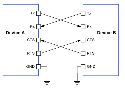
UART 设备以异步方式传输数据。因此，不使用时钟信号来同步发送端 UART 输出的位与接收端 UART 对位的采样。发送端 UART 在传输的数据包中添加起始位和停止位，而不是使用时钟信号。这些位定义了数据包的开始和结束。这样，接收端 UART 就知道何时开始读取这些位。当接收端 UART 检测到起始位时，它开始以一个称为波特率的特定频率读取传入的位。

<Frame>
  <img src="https://mintcdn.com/qualcomm-prod/rpHTx_a6zriKQll9/System/Interfaces/images/Data_transfer_uart.png?fit=max&auto=format&n=rpHTx_a6zriKQll9&q=85&s=eec251edb3d467cd9741f67e96734d8f" alt="两个 UART 设备之间的数据传输" width="417" height="307" data-path="System/Interfaces/images/Data_transfer_uart.png" />
</Frame>

<p align="center"><strong>图：两个 UART 设备之间的数据传输</strong></p>

决定传输成功与否的参数如下：

* **波特率**
* **起始位**
* **停止位**
* **奇偶校验位**
* **数据位**
* **流控**

下图显示了一个 UART 数据包示例。

<Frame>
  <img src="https://mintlify.s3.us-west-1.amazonaws.com/qualcomm-prod/zh/System/Interfaces/images/uart_data_packet.png" alt="UART 数据包" />
</Frame>

<p align="center"><strong>图：UART 数据包</strong></p>

## **UART 特性**

下表描述了各应用的 UART 传输模式。

<p align="center"><strong>表：UART 传输模式</strong></p>

<table style={tblA}>
  <thead>
    <tr>
      <th style={thAeq}>子系统</th>
      <th style={thAeq}>传输模式</th>
      <th style={thAeq}>说明</th>
    </tr>
  </thead>

  <tbody>
    <tr>
      <td style={tdA}>Linux</td>

      <td style={tdA}>
        <ul>
          <li>FIFO（低速）</li>
          <li>CPU DMA（高速）</li>
        </ul>
      </td>

      <td style={tdA}>
        <ul>
          <li>支持从 300 bps 到 4 Mbps 的波特率。</li>
          <li>FIFO 模式在其 Rx/Tx 缓冲区和系统内存之间传输数据。</li>
          <li>DMA 模式在其 Rx/Tx 缓冲区和系统内存之间传输数据。支持更高波特率和更大数据包的高速 UART 驱动可获得更好的性能。例如，Bluetooth 无线技术连接模块。</li>
        </ul>
      </td>
    </tr>

    <tr>
      <td style={tdA}>Boot</td>
      <td style={tdA}>FIFO</td>

      <td style={tdA}>
        <ul>
          <li>Rx/Tx 每字符 5 位到 8 位。</li>
          <li>支持的最大波特率为 115200。</li>
        </ul>
      </td>
    </tr>

    <tr>
      <td style={tdA}>aDSP</td>
      <td style={tdA}>FIFO</td>

      <td style={tdA}>
        <ul>
          <li>Rx/Tx 每字符 5 位到 8 位。</li>
          <li>支持的波特率：115200、230400、460800、921600、1000000、3000000 和 6000000。</li>
        </ul>
      </td>
    </tr>
  </tbody>
</table>

## **UART 接口组件**

下表提供了不同子系统的 UART 驱动配置路径。

**表：UART 接口：Linux**

<table style={tblA}>
  <thead>
    <tr>
      <th style={thA1}>文件类型</th>
      <th style={thA2}>说明</th>
    </tr>
  </thead>

  <tbody>
    <tr>
      <td style={tdA}>设备树源文件</td>

      <td style={tdA}>
        <ul>
          <li>QCS6490 和 QCS5430: [https://git.linaro.org/kernel-org/linux-next.git/tree/arch/arm64/boot/dts/qcom/sc7280.dtsi](https://git.linaro.org/kernel-org/linux-next.git/tree/arch/arm64/boot/dts/qcom/sc7280.dtsi)</li>
          <li>Dragonwing IQ-9075: [https://github.com/torvalds/linux/blob/master/arch/arm64/boot/dts/qcom/sa8775p.dtsi](https://github.com/torvalds/linux/blob/master/arch/arm64/boot/dts/qcom/sa8775p.dtsi)</li>
          <li>Dragonwing IQ-615: [https://git.kernel.org/pub/scm/linux/kernel/git/qcom/linux.git/tree/arch/arm64/boot/dts/qcom/qcs615.dtsi?h=arm64-for-6.16](https://git.kernel.org/pub/scm/linux/kernel/git/qcom/linux.git/tree/arch/arm64/boot/dts/qcom/qcs615.dtsi?h=arm64-for-6.16)</li>
        </ul>
      </td>
    </tr>

    <tr>
      <td style={tdA}>`Pinctrl` 设置</td>

      <td style={tdA}>
        <ul>
          <li>相应 QUP v3 串行引擎的引脚控制表位于 `<workspace_path_of_LINUX_kernel_image>/sources/kernel/kernel_platform/kernel/arch/arm64/boot/dts/qcom/<chipset>.dts`。</li>
          <li>有关用于覆盖芯片产品的 DTSI 配置示例，请参阅以下 DTSI 文件。 <ul><li>QCS6490 和 QCS5430: [https://git.linaro.org/kernel-org/linux-next.git/tree/arch/arm64/boot/dts/qcom/sc7280.dtsi](https://git.linaro.org/kernel-org/linux-next.git/tree/arch/arm64/boot/dts/qcom/sc7280.dtsi)</li><li>Dragonwing IQ-9075: [https://github.com/torvalds/linux/blob/master/arch/arm64/boot/dts/qcom/sa8775p.dtsi](https://github.com/torvalds/linux/blob/master/arch/arm64/boot/dts/qcom/sa8775p.dtsi)</li></ul></li>
          <li>Dragonwing IQ-615: [https://git.kernel.org/pub/scm/linux/kernel/git/qcom/linux.git/tree/arch/arm64/boot/dts/qcom/qcs615.dtsi?h=arm64-for-6.16](https://git.kernel.org/pub/scm/linux/kernel/git/qcom/linux.git/tree/arch/arm64/boot/dts/qcom/qcs615.dtsi?h=arm64-for-6.16)</li>
        </ul>
      </td>
    </tr>

    <tr>
      <td style={tdA}>Qualcomm TEE 设置</td>

      <td style={tdA}>
        <ul>
          <li>`/firmware/qualcomm-linux-spf-1-0_ap_standard_oem_nomodem/TZ.XF.5.0/trustzone_images/core/settings/buses/qup_accesscontrol/qupv3/config/<chipset>/QUPAC_Access.c`</li>
        </ul>
      </td>
    </tr>
  </tbody>
</table>

**表：UART 接口：Boot（仅 UEFI）**

<table style={tblA}>
  <thead>
    <tr>
      <th style={thA1}>文件类型</th>
      <th style={thA2}>说明</th>
    </tr>
  </thead>

  <tbody>
    <tr>
      <td style={tdA}>QUP v3 串行引擎配置</td>

      <td style={tdA}>
        <ul>
          <li>`/firmware/qualcomm-linux-spf-1-0_ap_standard_oem_nomodem/BOOT.MXF.1.0.c1/boot_images/boot/QcomPkg/SocPkg/<chipset>/Settings/UART/UartSettings.c`</li>
        </ul>
      </td>
    </tr>

    <tr>
      <td style={tdA}>Qualcomm TEE 设置</td>

      <td style={tdA}>
        <ul>
          <li>`/firmware/qualcomm-linux-spf-1-0_ap_standard_oem_nomodem/TZ.XF.5.0/trustzone_images/core/settings/buses/qup_accesscontrol/qupv3/config/<chipset>/QUPAC_Access.c`</li>
        </ul>
      </td>
    </tr>
  </tbody>
</table>

**表：UART 接口：aDSP/SLPI**

<table style={tblA}>
  <thead>
    <tr>
      <th style={thA1}>文件类型</th>
      <th style={thA2}>说明</th>
    </tr>
  </thead>

  <tbody>
    <tr>
      <td style={tdA}>QUP v3 串行引擎配置</td>

      <td style={tdA}>
        <ul>
          <li>`/firmware/qualcomm-linux-spf-1-0_ap_standard_oem_nomodem/ADSP.HT.5.5.c8/adsp_proc/core/settings/buses/qup_common/config/<chipset>/adsp/ssc/qup_devcfg.c`</li>
          <li>`/firmware/qualcomm-linux-spf-1-0_ap_standard_oem_nomodem/ADSP.HT.5.5.c8/adsp_proc/core/settings/buses/qup_fw/config/<chipset>/fw_devcfg.c`</li>
        </ul>
      </td>
    </tr>

    <tr>
      <td style={tdA}>固件配置设置</td>

      <td style={tdA}>
        <ul>
          <li>`/firmware/qualcomm-linux-spf-1-0_ap_standard_oem_nomodem/ADSP.HT.5.5.c8/adsp_proc/core/settings/buses/qup_fw/config/<chipset>/fw_devcfg.c`</li>
          <li>`/firmware/qualcomm-linux-spf-1-0_ap_standard_oem_nomodem/ADSP.HT.5.5.c8/adsp_proc/core/settings/buses/qup_fw/config/<chipset>/fw_devcfg.xml`</li>
        </ul>
      </td>
    </tr>
  </tbody>
</table>

### **UART API**

本节列出以下子系统的 UART API。

* Linux: [https://github.com/torvalds/linux/blob/master/include/linux/tty.h](https://github.com/torvalds/linux/blob/master/include/linux/tty.h)
* Boot: QcomPkg/Include/HSUart.h
* aDSP: adsp\_proc/core/api/buses/uart.h

## **UART 软件设备树配置**

本节介绍 UART 设备树配置以及设备节点的相关文档。

### **Linux**

有关内核设备实例的信息，请参阅 [https://github.com/torvalds/linux/blob/master/Documentation/devicetree/bindings/serial/qcom%2Cserial-geni-qcom.yaml](https://github.com/torvalds/linux/blob/master/Documentation/devicetree/bindings/serial/qcom%2Cserial-geni-qcom.yaml)。

有关 UART 驱动文件的信息，请参阅 [https://github.com/torvalds/linux/blob/master/drivers/tty/serial/qcom\_geni\_serial.c](https://github.com/torvalds/linux/blob/master/drivers/tty/serial/qcom_geni_serial.c)

```text theme={null}
uart7: serial@99c000 {
/* Manufacturer model of serial driver */
compatible = "qcom,geni-uart";
/* SE address and size */
reg = <0 0x0099c000 0 0x4000>;
/*Clocks for SE */
clocks = <&gcc GCC_QUPV3_WRAP0_S7_CLK>;
clock-names = "se";
/* pinctrl setting */
pinctrl-names = "default";
pinctrl-0 = <&qup_uart7_cts>, <&qup_uart7_rts>, <&qup_uart7_tx>, <&qup_uart7_rx>;
interrupts = <GIC_SPI 608 IRQ_TYPE_LEVEL_HIGH>;
power-domains = <&rpmhpd SC7280_CX>;
operating-points-v2 = <&qup_opp_table>;
interconnects = <&clk_virt MASTER_QUP_CORE_0 0 &clk_virt SLAVE_QUP_CORE_0 0>,
<&gem_noc MASTER_APPSS_PROC 0 &cnoc2 SLAVE_QUP_0 0>;
				interconnect-names = "qup-core", "qup-config";
/* To enable QUPV3 serial engine instance for UART protocol, change Status to OK */
				status = "disabled";
			};
		}
```

有关串行引擎 GPIO 的配置设置，请参阅以下 DTSI 文件。

* QCS6490 和 QCS5430: [https://git.linaro.org/kernel-org/linux-next.git/tree/arch/arm64/boot/dts/qcom/sc7280.dtsi](https://git.linaro.org/kernel-org/linux-next.git/tree/arch/arm64/boot/dts/qcom/sc7280.dtsi)
* Dragonwing IQ-9075: [https://github.com/torvalds/linux/blob/master/arch/arm64/boot/dts/qcom/sa8775p.dtsi](https://github.com/torvalds/linux/blob/master/arch/arm64/boot/dts/qcom/sa8775p.dtsi)
* Dragonwing IQ-615: [https://git.kernel.org/pub/scm/linux/kernel/git/qcom/linux.git/tree/arch/arm64/boot/dts/qcom/qcs615.dtsi?h=arm64-for-6.16](https://git.kernel.org/pub/scm/linux/kernel/git/qcom/linux.git/tree/arch/arm64/boot/dts/qcom/qcs615.dtsi?h=arm64-for-6.16)

```text theme={null}
qup_uart7_cts: qup-uart7-cts-state {
				pins = "gpio28";
				function = "qup07";
			};

			qup_uart7_rts: qup-uart7-rts-state {
				pins = "gpio29";
				function = "qup07";
			};

			qup_uart7_tx: qup-uart7-tx-state {
				pins = "gpio30";
				function = "qup07";
			};

			qup_uart7_rx: qup-uart7-rx-state {
				pins = "gpio31";
				function = "qup07";
			};
```

<Note>
  **注意**

  必须在 `QUPAC_Access.c` 文件中对齐 Qualcomm TEE 配置，以确保 GPIO/QUP v3 可用。您可以在 `/firmware/qualcomm-linux-spf-1-0_ap_standard_oem_nomodem/TZ.XF.5.0/trustzone_images/core/settings/buses/qup_accesscontrol/qupv3/config/<chipset>/QUPAC_Access.c` 访问 Qualcomm TEE 镜像。修改所需设置，或查看为 QUP v3 串行引擎特定实例分配的默认设置。
</Note>

QUP v3 同时支持启用流控的 4 线 UART 和不启用流控的 2 线 UART。以下 Qualcomm TEE 访问示例包含对两者的控制条目。启用 UART 协议的 QUP v3 串行引擎配置如下：

* 为 SE7 启用的默认配置（作为 HS UART）
  ```text theme={null}
  { QUPV3_0_SE7, QUPV3_PROTOCOL_UART_4W, QUPV3_MODE_FIFO, AC_HLOS, TRUE, TRUE, FALSE }, 
  ```
* SE5 的 2 线 UART 配置
  ```text theme={null}
  uart5: serial@994000 {
  compatible = "qcom,geni-uart";
  reg = <0 0x00994000 0 0x4000>;
  clocks = <&gcc GCC_QUPV3_WRAP0_S5_CLK>;
  clock-names = "se";
  pinctrl-names = "default";
  pinctrl-0 =  <&qup_uart5_tx>, <&qup_uart5_rx>;
  interrupts = <GIC_SPI 606 IRQ_TYPE_LEVEL_HIGH>;
  power-domains = <&rpmhpd SC7280_CX>;
  operating-points-v2 = <&qup_opp_table>;
  interconnects = <&clk_virt MASTER_QUP_CORE_0 0 &clk_virt SLAVE_QUP_CORE_0 0>,
      <&gem_noc MASTER_APPSS_PROC 0 &cnoc2 SLAVE_QUP_0 0>;
  interconnect-names = "qup-core", "qup-config";
  status = "disabled";
  };
  ```
  ```text theme={null}
  { QUPV3_0_SE5, QUPV3_PROTOCOL_UART_2W, QUPV3_MODE_FIFO,
  AC_HLOS, TRUE, FALSE, FALSE },
  ```

### **Boot**

可以使用 `/firmware/qualcomm-linux-spf-1-0_ap_standard_oem_nomodem/BOOT.MXF.1.0.c1/boot_images/boot/QcomPkg/SocPkg/<chipset>/Settings/UART/UartSettings.c` 文件在 boot 中将 QUP v3 串行引擎配置为 UART。

```text theme={null}
UART_PROPERTIES devices =
{
   // MAIN_PORT
   0x00994000,    // Serial Engine Base address
   0x009C0000,// qup_common base address
   0x2001c161,  // GPIO TX pin Config
   0x2000c171,  // GPIO RX Pin Config
   0,           // gpio_cts_config
   0,           // gpio_rfr_config
   0,           // clock_id_index
   (void*)0,        // bus_clock_id
   (void*)CLK_QUPV3_WRAP0_S5,     // core_clock_id
   0,          // irq number not used
   0,  //TCSR base
   0,  // TCSR offset
   0   // TCSR value

};
```

**GPIO 配置**

GPIO 配置在下表中列出。

**表：UART GPIO 配置**

<table style={tblA}>
  <thead>
    <tr>
      <th style={thAeq}>位</th>
      <th style={thAeq}>参数</th>
    </tr>
  </thead>

  <tbody>
    <tr>
      <td style={tdA}>\[0:3]</td>
      <td style={tdA}>GPIO 功能</td>
    </tr>

    <tr>
      <td style={tdA}>\[4:13]</td>
      <td style={tdA}>GPIO 编号</td>
    </tr>

    <tr>
      <td style={tdA}>\[14]</td>
      <td style={tdA}>方向</td>
    </tr>

    <tr>
      <td style={tdA}>\[15:17]</td>
      <td style={tdA}>上下拉类型</td>
    </tr>

    <tr>
      <td style={tdA}>\[18:21]</td>
      <td style={tdA}>驱动强度</td>
    </tr>
  </tbody>
</table>

必须根据以下位域配置每个 GPIO。

```text theme={null}
<!--
GPIO configuration calculation

GPIO DIR values
GPIO_INPUT = 0x0
GPIO_OUTPUT = 0x1

GPIO_PULL values
GPIO_NO_PULL = 0, /**< -- Do not specify a pull. */
GPIO_PULL_DOWN = 0x1, /**< -- Pull the GPIO down. */
GPIO_KEEPER_ENABLE = 0x2, /**< -- Keeper Enable. */
GPIO_PULL_UP = 0x3, /**< -- Pull the GPIO up. */

GPIO_DRV_STRENGTH values
GPIO_2P0MA = 0, /**< -- Specify a 2 mA drive. */
GPIO_4P0MA = 0x1, /**< -- Specify a 4 mA drive. */
GPIO_6P0MA = 0x2, /**< -- Specify a 6 mA drive. */
GPIO_8P0MA = 0x3, /**< -- Specify a 8 mA drive. */

GPIO_FUNC_SELECT_Value
GPIO_FS_VAL =0, //Specifies GPIO function

GPIO_FS_VAL =0X1, //Specify NON GPIO function( UART/SPI/I2C)
	
GPIO configuration = (GPIO_NUM & 0xFF) << 0x10 |
(GPIO_FS_VAL & 0xF) << 0xC |
(GPIO_DRV_STRENGTH & 0xF) << 0x8 |
(GPIO_PULL & 0xF) << 0x4 |
(GPIO_DIR & 0xF)

-->
/*
| RESERVED | GPIO NUM | DRIVE | FUNC | PULL | DIR |
-------------------------------------------------------------------------
| 0000 | 0000 | 0001 | 1110 | 0001 | 0001 | 0010 | 0001 |
-------------------------------------------------------------------------
*/
```

### **aDSP**

固件在 aDSP 子系统的启动序列期间加载 SSC QUP。因此，配置文件位于 aDSP 构建中的 `/firmware/qualcomm-linux-spf-1-0_ap_standard_oem_nomodem/ADSP.HT.5.5.c8/adsp_proc/core/settings/buses/qup_fw/config/<chipset>/fw_devcfg.c`。

以下配置是 SSC QUP SE5/6 以 FIFO 模式加载 UART 固件的示例。

```text theme={null}
                   offset,        protocol,   mode,  load_fw, dfs_mode
se_cfg se0_cfg = { 0x80000, SE_PROTOCOL_I3C,    GSI,     TRUE, TRUE  };
se_cfg se1_cfg = { 0x84000, SE_PROTOCOL_I2C,    GSI,     TRUE, TRUE  };
se_cfg se2_cfg = { 0x88000, SE_PROTOCOL_I2C,    GSI,     TRUE, TRUE  };
se_cfg se3_cfg = { 0x8C000, SE_PROTOCOL_I2C,    GSI,     FALSE, TRUE  };
se_cfg se4_cfg = { 0x90000, SE_PROTOCOL_SPI,    GSI,     TRUE, TRUE };
se_cfg se5_cfg = { 0x94000, SE_PROTOCOL_UART,   FIFO,    TRUE,FALSE };
se_cfg se6_cfg = { 0x98000, SE_PROTOCOL_UART,   FIFO,    TRUE,FALSE  };
```

GPIO 配置：QUP 通用驱动中的每个串行引擎都按协议配置了默认 GPIO 配置。QUP v3 通用驱动根据串行引擎中加载的协议，从 `/firmware/qualcomm-linux-spf-1-0_ap_standard_oem_nomodem/ADSP.HT.5.5.c8/adsp_proc/core/settings/buses/qup_common/config/<chipset>/adsp/ssc/qup_instance_mapping.c` 中获取 GPIO 配置。

默认 GPIO 配置可按如下方式覆盖。

```text theme={null}
{      .instance_id          =  6 ,         //Instance ID
        .qup              =  QUP_SSC,    //QUP Type
        .se_index         =  5,          //SE ID
        .se_data          =  NULL,       //devcfg_map
        .protocol_io_cfg  =  {
                                TLMM_MAP(TLMM_GPIO_KEEPER ,TLMM_GPIO_2MA,TLMM_GPIO_KEEPER ),              //SLEEP CFG
                                TLMM_MAP(TLMM_GPIO_NO_PULL,TLMM_GPIO_6MA,TLMM_GPIO_KEEPER ),              //SPI CFG
                                TLMM_MAP(TLMM_GPIO_NO_PULL,TLMM_GPIO_2MA,TLMM_GPIO_NO_PULL),              //UART CFG
                                TLMM_MAP(TLMM_GPIO_PULL_UP,TLMM_GPIO_2MA,TLMM_GPIO_NO_PULL),              //I2C CFG
                                TLMM_MAP(TLMM_GPIO_PULL_UP,TLMM_GPIO_2MA,TLMM_GPIO_KEEPER )               //I3C CFG
                             },
        .se_exclusive     =  TRUE,
}
```

TLMM\_MAP 是用于初始化活动和休眠状态 GPIO 配置的宏。例如，TLMM\_MAP 宏的示例用法。

```text theme={null}
TLMM_MAP (active state pull type, drive strength, sleep state pull type)
```

## **UART 工具**

本节介绍用于确认 UART 数据传输的 UART 串行接口驱动的各种测试工具和方法。

### **Linux**

有关更多详细信息，请参阅 [https://docs.kernel.org/admin-guide/serial-console.html](https://docs.kernel.org/admin-guide/serial-console.html)。

## **在内核中启用 UART**

本节介绍如何在内核中启用 UART。

### **Linux**

支持 UART 接口需要以下驱动内核配置。

* UART 驱动：[https://github.com/torvalds/linux/blob/master/drivers/tty/serial/qcom\_geni\_serial.c](https://github.com/torvalds/linux/blob/master/drivers/tty/serial/qcom_geni_serial.c)
* 内核 `defconfig` 文件路径：`<workspace_path_of_LINUX_kernel_image>/sources/kernel/kernel_platform/kernel/arch/arm64/configs/qcom_defconfig`

启用以下内核配置。

* `CONFIG_QCOM_GENI_SE=y`
* `CONFIG_SERIAL_QCOM_GENI=y`

要为环回验证启用串行节点，请在 `/arch/arm64/boot/dts/qcom/<chipset>.dtsi` 文件中应用以下补丁。

```text theme={null}
--- a/arch/arm64/boot/dts/qcom/<chipset>.dtsi
+++ b/arch/arm64/boot/dts/qcom/<chipset>.dtsi
@@ -70,6 +70,7 @@
 		spi13 = &spi13;
 		spi14 = &spi14;
 		spi15 = &spi15;
+		serial1 = &uart7;
}; 


+
+&uart7 {
+	status = "ok";
+}; 
```

<Note>
  **注意**

  您应当编译内核配置和设备树更改。编译完成后，可以将镜像加载到设备以验证接口。有关接口验证的信息，请参阅[验证 UART 接口](https://dragonwingdocs.qualcomm.com/System/Interfaces/uart#verify-uart-interface)一节。
</Note>

### **Boot/aDSP**

有关自定义，请参阅 [UART 软件设备树配置](https://dragonwingdocs.qualcomm.com/System/Interfaces/uart#uart-software-device-tree-configuration)一节。

## **UART 自定义**

有关自定义 UART 软件的信息，请参阅 [QUP v3 访问控制自定义](https://dragonwingdocs.qualcomm.com/System/Interfaces/references#qup-v3-access-control-customization)。

## **验证 UART 接口**

本节介绍 UART 驱动的验证流程，以及 Qualcomm 驱动的测试结果。

### **Linux**

要启用 UART 节点，请执行以下操作并编译内核配置。

1. 要将 UART 状态更改为 **OK** 并为特定 UART 节点添加别名，请编辑以下 DTSI 文件。

   * QCS6490 和 QCS5430: [https://git.linaro.org/kernel-org/linux-next.git/tree/arch/arm64/boot/dts/qcom/sc7280.dtsi](https://git.linaro.org/kernel-org/linux-next.git/tree/arch/arm64/boot/dts/qcom/sc7280.dtsi)
   * Dragonwing IQ-9075: [https://github.com/torvalds/linux/blob/master/arch/arm64/boot/dts/qcom/sa8775p.dtsi](https://github.com/torvalds/linux/blob/master/arch/arm64/boot/dts/qcom/sa8775p.dtsi)
   * Dragonwing IQ-615: [https://git.kernel.org/pub/scm/linux/kernel/git/qcom/linux.git/tree/arch/arm64/boot/dts/qcom/qcs615.dtsi?h=arm64-for-6.16](https://git.kernel.org/pub/scm/linux/kernel/git/qcom/linux.git/tree/arch/arm64/boot/dts/qcom/qcs615.dtsi?h=arm64-for-6.16)

   <Note>
     **注意**

     启用 SSH shell 或使用 ADB shell 运行命令并在 SSH shell（控制台）窗口中显示输出。有关如何运行 SSH 的更多信息，请参阅[使用 SSH](https://docs.qualcomm.com/bundle/publicresource/topics/80-80021-254/how_to.html) 一节。
   </Note>

   ```text theme={null}
   aliases {
   i2c0 = &i2c0;
   spi15 = &spi15;
   ++serial1 = &uart7;
   };
   uart7: serial@99c000 {
   compatible = "qcom,geni-uart";
   reg = <0 0x0099c000 0 0x4000>;
   clocks = <&gcc GCC_QUPV3_WRAP0_S7_CLK>;
   clock-names = "se";
   pinctrl-names = "default";
   pinctrl-0 = <&qup_uart7_cts>, <&qup_uart7_rts>, <&qup_uart7_tx>,
   <&qup_uart7_rx>;
   interrupts = <GIC_SPI 608 IRQ_TYPE_LEVEL_HIGH>;
   power-domains = <&rpmhpd SC7280_CX>;
   operating-points-v2 = <&qup_opp_table>;
   interconnects = <&clk_virt MASTER_QUP_CORE_0 0 &clk_virt SLAVE_QUP_CORE_0
   0>,
   <&gem_noc MASTER_APPSS_PROC 0 &cnoc2 SLAVE_QUP_0 0>;
   interconnect-names = "qup-core", "qup-config";
   ++status = "ok";
   };
   ```
2. 为进行环回测试，在 [https://github.com/torvalds/linux/blob/master/drivers/tty/serial/qcom\_geni\_serial.c](https://github.com/torvalds/linux/blob/master/drivers/tty/serial/qcom_geni_serial.c) 文件中的 `qcom_geni_serial.c` 里禁用 `if` 条件。
   ```text theme={null}
   //if (mctrl & TIOCM_LOOP) // Disabling the if condition for loopback test
   port->loopback = RX_TX_CTS_RTS_SORTED;
   ```

要验证 Linux 内核中的 QUP v3 UART 注册功能，请确保 UART 已正确注册到 TTY 栈。

1. 在以下 DTSI 文件中禁用 UART 默认用例。
   * QCS6490 和 QCS5430: [https://git.linaro.org/kernel-org/linux-next.git/tree/arch/arm64/boot/dts/qcom/sc7280.dtsi](https://git.linaro.org/kernel-org/linux-next.git/tree/arch/arm64/boot/dts/qcom/sc7280.dtsi)
   * Dragonwing IQ-9075: [https://github.com/torvalds/linux/blob/master/arch/arm64/boot/dts/qcom/sa8775p.dtsi](https://github.com/torvalds/linux/blob/master/arch/arm64/boot/dts/qcom/sa8775p.dtsi)
   * Dragonwing IQ-615: [https://git.kernel.org/pub/scm/linux/kernel/git/qcom/linux.git/tree/arch/arm64/boot/dts/qcom/qcs615.dtsi?h=arm64-for-6.16](https://git.kernel.org/pub/scm/linux/kernel/git/qcom/linux.git/tree/arch/arm64/boot/dts/qcom/qcs615.dtsi?h=arm64-for-6.16)
   ```text theme={null}
   bluetooth: bluetooth {
          ++      status = "disabled";
   ```
   将显示以下输出。
   ```text theme={null}
   ls /dev/ttyHS1
   /dev/ttyHS1
   dmesg | grep ttyH
   [    3.355487] 99c000.serial: ttyHS1 at MMIO 0x99c000 (irq = 137, base_baud = 0) is a MSM
   ```
2. 要验证 UART 驱动，请执行以下操作：
   1. 以 permissive 模式打开 SSH shell 或使用 ADB shell。
   2. 注册 UART。
      ```text theme={null}
      ls /dev/ttyHS*
      ```
      以下是示例输出。
      ```text theme={null}
      ls /dev/ttyHS*
      /dev/ttyHS1
      ```
      根据为 `serial1 = &uart7` 添加的别名映射 `ttyHS1` 端口，并启用串行引擎。

内核中注册的 UART 设备将被列出。UART 驱动按照测试序列启用环回。在 DUT 中启用 UART 节点后，运行以下命令验证 DTSI 文件中已启用 UART 实例。

<Note>
  **注意**

  打开两个 SSH shell 或使用 ADB shell，为 UART 环回写入和读取数据。有关如何运行 SSH 的更多信息，请参阅[使用 SSH](https://docs.qualcomm.com/bundle/publicresource/topics/80-80021-254/how_to.html) 一节。
</Note>

1. 以 permissive 模式打开 SSH shell 或使用 ADB shell。
2. 使用 `echo` 命令传输数据。
   ```text theme={null}
   echo "This Document Is Very Much Helpful" > /dev/ttyHS1
   ```
3. 在 UART 设备节点中读取数据。
   ```text theme={null}
   cat /dev/ttyHS1
   ```

## **调试 UART 问题**

本节介绍如何在 UART 软件驱动中启用调试日志。

### **Linux**

UART 驱动日志通过动态调试方法启用。在 `<workspace_path_of_LINUX_kernel_image>/sources/kernel/kernel_platform/kernel/arch/arm64/configs/qcom_defconfig` 中启用 `CONFIG_DYNAMIC_DEBUG`，以支持内核驱动的动态调试。

要在内核日志（`dmesg`）中启用并查看 UART 驱动日志，请运行以下命令。

```text theme={null}
mount -t debugfs none /sys/kernel/debug
echo -n "file qcom_geni_serial.c +p" > /sys/kernel/debug/dynamic_debug/control
echo -n "file qcom-geni-se.c +p" > /sys/kernel/debug/dynamic_debug/control
echo -n "file serial_core.c +p" > /sys/kernel/debug/dynamic_debug/control
echo -n "file gpi.c +p" > /sys/kernel/debug/dynamic_debug/control
```

## **UART 示例**

有关上游设备树参考的信息，请参阅以下 DTSI 文件。

* QCS6490 和 QCS5430: [https://git.linaro.org/kernel-org/linux-next.git/tree/arch/arm64/boot/dts/qcom/sc7280.dtsi](https://git.linaro.org/kernel-org/linux-next.git/tree/arch/arm64/boot/dts/qcom/sc7280.dtsi)
* Dragonwing IQ-9075: [https://github.com/torvalds/linux/blob/master/arch/arm64/boot/dts/qcom/sa8775p.dtsi](https://github.com/torvalds/linux/blob/master/arch/arm64/boot/dts/qcom/sa8775p.dtsi)
* Dragonwing IQ-615: [https://git.kernel.org/pub/scm/linux/kernel/git/qcom/linux.git/tree/arch/arm64/boot/dts/qcom/qcs615.dtsi?h=arm64-for-6.16](https://git.kernel.org/pub/scm/linux/kernel/git/qcom/linux.git/tree/arch/arm64/boot/dts/qcom/qcs615.dtsi?h=arm64-for-6.16)

有关 Qualcomm Linux 硬件 SoC 设备树节点的信息，请参阅以下 DTSI 文件。

* QCS6490 和 QCS5430: [https://git.linaro.org/kernel-org/linux-next.git/tree/arch/arm64/boot/dts/qcom/qcs6490-rb3gen2.dts](https://git.linaro.org/kernel-org/linux-next.git/tree/arch/arm64/boot/dts/qcom/qcs6490-rb3gen2.dts)
* Dragonwing IQ-9075: [https://github.com/torvalds/linux/blob/master/arch/arm64/boot/dts/qcom/sa8775p.dtsi](https://github.com/torvalds/linux/blob/master/arch/arm64/boot/dts/qcom/sa8775p.dtsi)
* Dragonwing IQ-615: [https://git.kernel.org/pub/scm/linux/kernel/git/qcom/linux.git/tree/arch/arm64/boot/dts/qcom/qcs615.dtsi?h=arm64-for-6.16](https://git.kernel.org/pub/scm/linux/kernel/git/qcom/linux.git/tree/arch/arm64/boot/dts/qcom/qcs615.dtsi?h=arm64-for-6.16)