> ## Documentation Index
> Fetch the complete documentation index at: https://dragonwingdocs.qualcomm.com/llms.txt
> Use this file to discover all available pages before exploring further.
# 40 针低速连接器
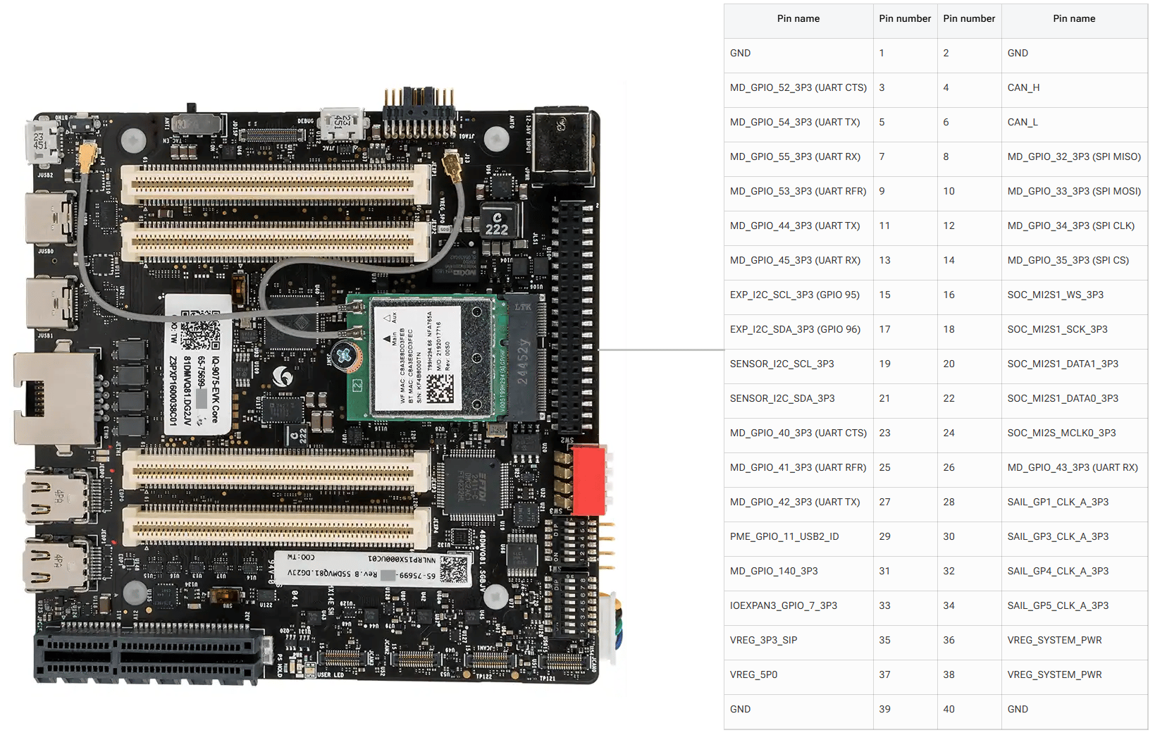
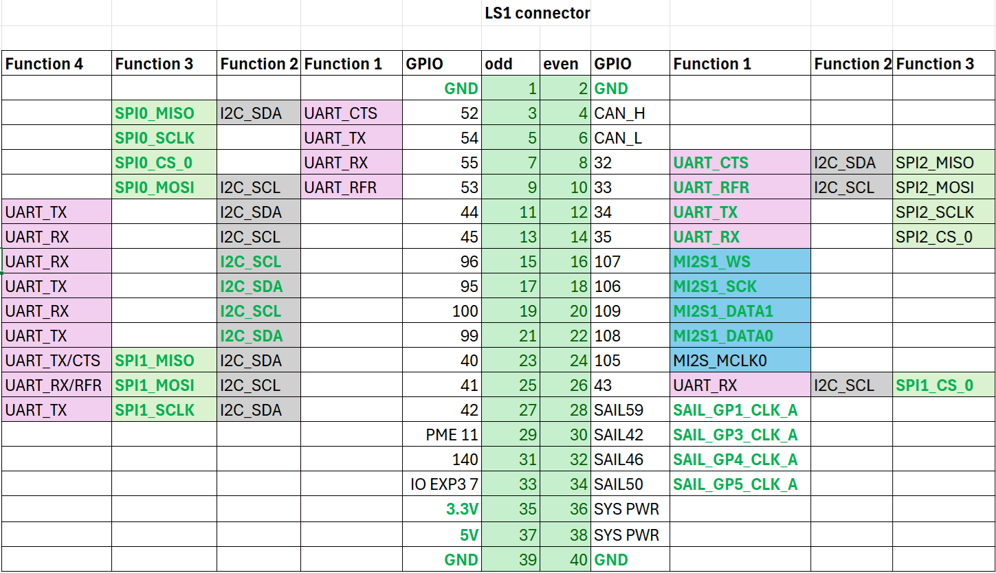
Dragonwing IQ9-EVK 包含一个低速连接器(JLS1),提供对各种 GPIO、CAN、QUP 及其他接口的访问。
## 引脚定义
下图展示了 IQ-9075 EVK 40 针 LS 连接器的默认功能。
 ## GPIO
以下命令需要 root 权限。使用 `sudo su` 切换到 root 用户。
### 确定 GPIO 子系统编号
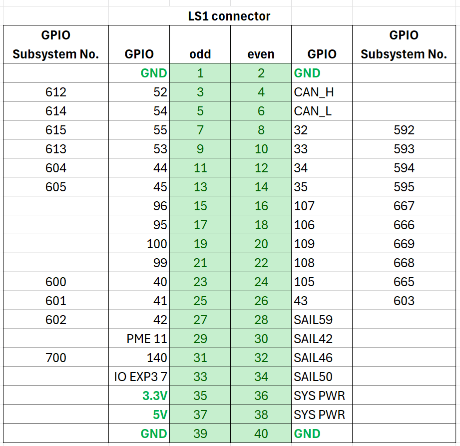
运行以下命令并查找 `platform/f000000.pinctrl`(gpiochip4)以确定 GPIO 基准编号。对于 IQ-9075,基准值为 **560**。
```bash theme={null}
cat /sys/kernel/debug/gpio
```
**示例:** 对于 LS 连接器引脚 5,GPIO 编号为 54。GPIO 子系统编号为:560 + 54 = **614**。
## GPIO
以下命令需要 root 权限。使用 `sudo su` 切换到 root 用户。
### 确定 GPIO 子系统编号
运行以下命令并查找 `platform/f000000.pinctrl`(gpiochip4)以确定 GPIO 基准编号。对于 IQ-9075,基准值为 **560**。
```bash theme={null}
cat /sys/kernel/debug/gpio
```
**示例:** 对于 LS 连接器引脚 5,GPIO 编号为 54。GPIO 子系统编号为:560 + 54 = **614**。
 ### 通过 sysfs 控制 GPIO
```bash theme={null}
cd /sys/class/gpio
echo 614 > export
```
```bash theme={null}
cd gpio614
echo out > direction
echo 1 > value
```
| 属性 | 值 |
| ----------- | -------------------------------- |
| `direction` | `in`(输入)、`out`(输出) |
| `value` | `0`(低电平)、`1`(高电平) |
| `edge` | `rising`、`falling`、`both`、`none` |
```bash theme={null}
cd ..
echo 614 > unexport
```
### GPIO 代码示例
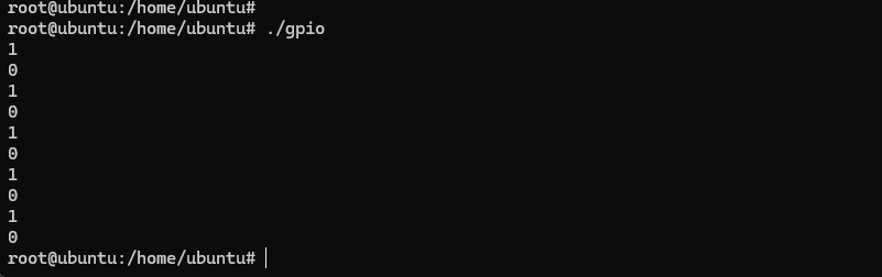
以下示例将引脚 5 设置为输出、引脚 7 设置为输入,并循环检测引脚 7 的电平。
```c theme={null}
#include
#include
#include
int out_gpio = 614;
int in_gpio = 615;
int main() {
char export_path[50] = {};
char export_command[100] = {};
snprintf(export_path, sizeof(export_path), "/sys/class/gpio/export");
snprintf(export_command, sizeof(export_command), "echo %d > %s ", out_gpio, export_path);
system(export_command);
snprintf(export_command, sizeof(export_command), "echo %d > %s ", in_gpio, export_path);
system(export_command);
char direction_path[50] = {};
snprintf(direction_path, sizeof(direction_path), "/sys/class/gpio/gpio%d/direction", out_gpio);
FILE *direction_file = fopen(direction_path, "w");
if (direction_file == NULL) { perror("Failed to open GPIO direction file"); return -1; }
fprintf(direction_file, "out");
fclose(direction_file);
snprintf(direction_path, sizeof(direction_path), "/sys/class/gpio/gpio%d/direction", in_gpio);
direction_file = fopen(direction_path, "w");
if (direction_file == NULL) { perror("Failed to open GPIO direction file"); return -1; }
fprintf(direction_file, "in");
fclose(direction_file);
char value_in_path[50] = {};
char value_out_path[50] = {};
char cat_command[100] = {};
snprintf(value_out_path, sizeof(value_out_path), "/sys/class/gpio/gpio%d/value", out_gpio);
snprintf(value_in_path, sizeof(value_in_path), "/sys/class/gpio/gpio%d/value", in_gpio);
snprintf(cat_command, sizeof(cat_command), "cat %s", value_in_path);
FILE *value_out_file = fopen(value_out_path, "w");
if (value_out_file == NULL) { perror("Failed to open GPIO value file"); return -1; }
for (int i = 0; i < 5; i++) {
fprintf(value_out_file, "1"); fflush(value_out_file);
system(cat_command); sleep(1);
fprintf(value_out_file, "0"); fflush(value_out_file);
system(cat_command); sleep(1);
}
fclose(value_out_file);
char unexport_path[50] = {};
char unexport_command[100] = {};
snprintf(unexport_path, sizeof(unexport_path), "/sys/class/gpio/unexport");
snprintf(unexport_command, sizeof(unexport_command), "echo %d > %s ", out_gpio, unexport_path);
system(unexport_command);
snprintf(unexport_command, sizeof(unexport_command), "echo %d > %s ", in_gpio, unexport_path);
system(unexport_command);
return 0;
}
```
```bash theme={null}
gcc gpio.c -o gpio
```
使用杜邦线短接引脚 5 和引脚 7。
### 通过 sysfs 控制 GPIO
```bash theme={null}
cd /sys/class/gpio
echo 614 > export
```
```bash theme={null}
cd gpio614
echo out > direction
echo 1 > value
```
| 属性 | 值 |
| ----------- | -------------------------------- |
| `direction` | `in`(输入)、`out`(输出) |
| `value` | `0`(低电平)、`1`(高电平) |
| `edge` | `rising`、`falling`、`both`、`none` |
```bash theme={null}
cd ..
echo 614 > unexport
```
### GPIO 代码示例
以下示例将引脚 5 设置为输出、引脚 7 设置为输入,并循环检测引脚 7 的电平。
```c theme={null}
#include
#include
#include
int out_gpio = 614;
int in_gpio = 615;
int main() {
char export_path[50] = {};
char export_command[100] = {};
snprintf(export_path, sizeof(export_path), "/sys/class/gpio/export");
snprintf(export_command, sizeof(export_command), "echo %d > %s ", out_gpio, export_path);
system(export_command);
snprintf(export_command, sizeof(export_command), "echo %d > %s ", in_gpio, export_path);
system(export_command);
char direction_path[50] = {};
snprintf(direction_path, sizeof(direction_path), "/sys/class/gpio/gpio%d/direction", out_gpio);
FILE *direction_file = fopen(direction_path, "w");
if (direction_file == NULL) { perror("Failed to open GPIO direction file"); return -1; }
fprintf(direction_file, "out");
fclose(direction_file);
snprintf(direction_path, sizeof(direction_path), "/sys/class/gpio/gpio%d/direction", in_gpio);
direction_file = fopen(direction_path, "w");
if (direction_file == NULL) { perror("Failed to open GPIO direction file"); return -1; }
fprintf(direction_file, "in");
fclose(direction_file);
char value_in_path[50] = {};
char value_out_path[50] = {};
char cat_command[100] = {};
snprintf(value_out_path, sizeof(value_out_path), "/sys/class/gpio/gpio%d/value", out_gpio);
snprintf(value_in_path, sizeof(value_in_path), "/sys/class/gpio/gpio%d/value", in_gpio);
snprintf(cat_command, sizeof(cat_command), "cat %s", value_in_path);
FILE *value_out_file = fopen(value_out_path, "w");
if (value_out_file == NULL) { perror("Failed to open GPIO value file"); return -1; }
for (int i = 0; i < 5; i++) {
fprintf(value_out_file, "1"); fflush(value_out_file);
system(cat_command); sleep(1);
fprintf(value_out_file, "0"); fflush(value_out_file);
system(cat_command); sleep(1);
}
fclose(value_out_file);
char unexport_path[50] = {};
char unexport_command[100] = {};
snprintf(unexport_path, sizeof(unexport_path), "/sys/class/gpio/unexport");
snprintf(unexport_command, sizeof(unexport_command), "echo %d > %s ", out_gpio, unexport_path);
system(unexport_command);
snprintf(unexport_command, sizeof(unexport_command), "echo %d > %s ", in_gpio, unexport_path);
system(unexport_command);
return 0;
}
```
```bash theme={null}
gcc gpio.c -o gpio
```
使用杜邦线短接引脚 5 和引脚 7。
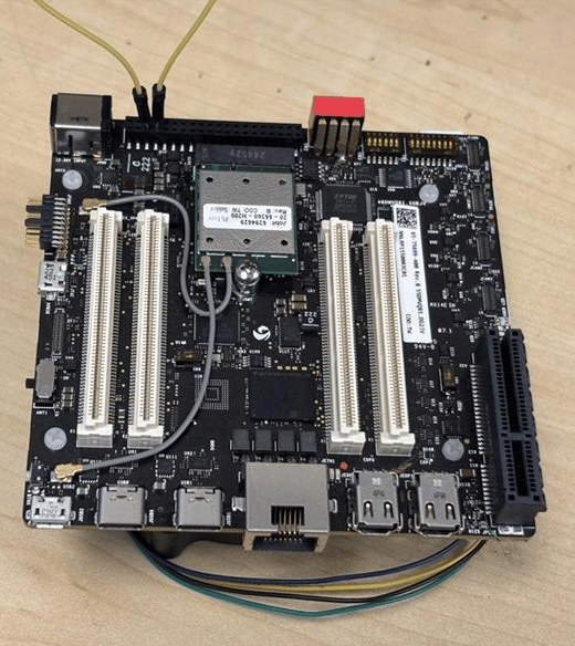 注意引脚顺序。请勿短接电源和地引脚 — 这可能会损坏板卡。
```bash theme={null}
./gpio
```
注意引脚顺序。请勿短接电源和地引脚 — 这可能会损坏板卡。
```bash theme={null}
./gpio
```
 安装 `python3-periphery`:
```bash theme={null}
apt install python3-pip
apt install python3-periphery
```
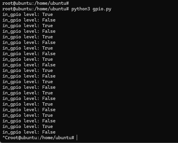
以下示例将引脚 5 设置为输出、引脚 7 设置为输入,并循环检测引脚 7 的电平。
```python theme={null}
from periphery import GPIO
import time
out_gpio = GPIO(614, "out")
in_gpio = GPIO(615, "in")
try:
while True:
try:
out_gpio.write(True)
print(f"in_gpio level: {in_gpio.read()}")
out_gpio.write(False)
print(f"in_gpio level: {in_gpio.read()}")
time.sleep(1)
except KeyboardInterrupt:
out_gpio.write(False)
break
except IOError:
print("Error")
finally:
out_gpio.close()
in_gpio.close()
```
使用杜邦线短接引脚 5 和引脚 7。
注意引脚顺序。请勿短接电源和地引脚 — 这可能会损坏板卡。
```bash theme={null}
python3 gpio.py
```
安装 `python3-periphery`:
```bash theme={null}
apt install python3-pip
apt install python3-periphery
```
以下示例将引脚 5 设置为输出、引脚 7 设置为输入,并循环检测引脚 7 的电平。
```python theme={null}
from periphery import GPIO
import time
out_gpio = GPIO(614, "out")
in_gpio = GPIO(615, "in")
try:
while True:
try:
out_gpio.write(True)
print(f"in_gpio level: {in_gpio.read()}")
out_gpio.write(False)
print(f"in_gpio level: {in_gpio.read()}")
time.sleep(1)
except KeyboardInterrupt:
out_gpio.write(False)
break
except IOError:
print("Error")
finally:
out_gpio.close()
in_gpio.close()
```
使用杜邦线短接引脚 5 和引脚 7。
注意引脚顺序。请勿短接电源和地引脚 — 这可能会损坏板卡。
```bash theme={null}
python3 gpio.py
```
 ## UART
引脚 5 和 7 默认配置为 UART(GPIO 线 54 和 55,映射到 `uart12 = qup1_se5 (0xa98000)`)。
按照[修改串行引擎节点](./peripheral_interface_overview#modify-serial-engine-node)的步骤启用 UART 接口。启用后,设备节点出现在 `/dev/ttyHS3`。
```bash theme={null}
ubuntu@ubuntu:/dev$ ls -al ttyHS3
crw-rw---- 1 root dialout 236, 2 Nov 25 18:16 ttyHS3
```
使用杜邦线短接引脚 5 和引脚 7。
注意引脚顺序。请勿短接电源和地引脚 — 这可能会损坏板卡。
```bash theme={null}
sudo stty -F /dev/ttyHS3 ispeed 115200 ospeed 115200
sudo stty -F /dev/ttyHS3 115200 -echo -icanon -isig -iexten -icrnl -ixon -opost
```
**终端 1(RX):**
```bash theme={null}
sudo cat /dev/ttyHS3
```
**终端 2(TX):**
```bash theme={null}
sudo su
echo "hello world!" > /dev/ttyHS3
```
## UART
引脚 5 和 7 默认配置为 UART(GPIO 线 54 和 55,映射到 `uart12 = qup1_se5 (0xa98000)`)。
按照[修改串行引擎节点](./peripheral_interface_overview#modify-serial-engine-node)的步骤启用 UART 接口。启用后,设备节点出现在 `/dev/ttyHS3`。
```bash theme={null}
ubuntu@ubuntu:/dev$ ls -al ttyHS3
crw-rw---- 1 root dialout 236, 2 Nov 25 18:16 ttyHS3
```
使用杜邦线短接引脚 5 和引脚 7。
注意引脚顺序。请勿短接电源和地引脚 — 这可能会损坏板卡。
```bash theme={null}
sudo stty -F /dev/ttyHS3 ispeed 115200 ospeed 115200
sudo stty -F /dev/ttyHS3 115200 -echo -icanon -isig -iexten -icrnl -ixon -opost
```
**终端 1(RX):**
```bash theme={null}
sudo cat /dev/ttyHS3
```
**终端 2(TX):**
```bash theme={null}
sudo su
echo "hello world!" > /dev/ttyHS3
```
 以下 C 程序通过 UART 发送和接收数据,包含完整的原始模式配置和可选的 PM 时钟投票支持。
```c theme={null}
#define _GNU_SOURCE
#include
#include
#include
#include
#include
#include
#include
#include
#include
#include
#include
#ifndef TIOCPMGET
#define TIOCPMGET 0x544D
#endif
#ifndef TIOCPMPUT
#define TIOCPMPUT 0x544E
#endif
static volatile sig_atomic_t g_stop = 0;
static void on_sigint(int sig) { (void)sig; g_stop = 1; }
static speed_t baud_to_speed(int baud) {
switch (baud) {
case 9600: return B9600;
case 19200: return B19200;
case 38400: return B38400;
case 57600: return B57600;
case 115200: return B115200;
case 230400: return B230400;
default: return 0;
}
}
static void uart_clock_vote_on(int fd) {
if (ioctl(fd, TIOCPMGET, 0) < 0 && errno != ENOTTY)
fprintf(stderr, "WARN: ioctl(TIOCPMGET) failed: %s\n", strerror(errno));
}
static void uart_clock_vote_off(int fd) {
if (ioctl(fd, TIOCPMPUT, 0) < 0 && errno != ENOTTY)
fprintf(stderr, "WARN: ioctl(TIOCPMPUT) failed: %s\n", strerror(errno));
}
static int configure_serial(int fd, int baud, int rx_block_forever) {
struct termios tty;
if (tcgetattr(fd, &tty) != 0) { perror("tcgetattr"); return -1; }
cfmakeraw(&tty);
speed_t spd = baud_to_speed(baud);
if (spd == 0) { fprintf(stderr, "Unsupported baud rate: %d\n", baud); return -1; }
cfsetispeed(&tty, spd); cfsetospeed(&tty, spd);
tty.c_cflag &= ~(PARENB | CSTOPB | CSIZE); tty.c_cflag |= CS8 | CLOCAL | CREAD | ~CRTSCTS;
tty.c_iflag &= ~(IXON | IXOFF | IXANY);
tty.c_cc[VMIN] = rx_block_forever ? 1 : 0;
tty.c_cc[VTIME] = 0;
if (tcsetattr(fd, TCSANOW, &tty) != 0) { perror("tcsetattr"); return -1; }
tcflush(fd, TCIOFLUSH);
return 0;
}
int main(int argc, char **argv) {
struct sigaction sa; memset(&sa, 0, sizeof(sa));
sa.sa_handler = on_sigint; sigaction(SIGINT, &sa, NULL);
const char *device = "/dev/ttyHS3";
int baud = 115200, rx_mode = 0;
const char *tx = "hello world!\n";
int c;
while ((c = getopt(argc, argv, "d:b:t:Rh")) != -1) {
switch (c) {
case 'd': device = optarg; break;
case 'b': baud = atoi(optarg); break;
case 't': tx = optarg; break;
case 'R': rx_mode = 1; break;
}
}
int fd = open(device, O_RDWR | O_NOCTTY);
if (fd < 0) { fprintf(stderr, "Failed to open %s: %s\n", device, strerror(errno)); return 1; }
if (configure_serial(fd, baud, rx_mode) != 0) { close(fd); return 1; }
if (rx_mode) {
struct pollfd pfd = { .fd = fd, .events = POLLIN };
uart_clock_vote_on(fd);
printf("RX: waiting on %s (Ctrl+C to stop)...\n", device);
while (!g_stop) {
if (poll(&pfd, 1, -1) < 0) { if (errno == EINTR) continue; break; }
if (pfd.revents & POLLIN) {
unsigned char buf[512];
ssize_t r = read(fd, buf, sizeof(buf));
if (r > 0) { fwrite(buf, 1, r, stdout); fflush(stdout); }
}
}
uart_clock_vote_off(fd);
} else {
uart_clock_vote_on(fd);
ssize_t w = write(fd, tx, strlen(tx));
printf("TX (%zd bytes) on %s: %s", w, device, tx);
uart_clock_vote_off(fd);
}
close(fd);
return 0;
}
```
```bash theme={null}
gcc -O2 -Wall -o uarttest uart.c
```
**终端 1(RX):**
```bash theme={null}
sudo ./uarttest --rx -b 115200 -d /dev/ttyHS3
```
**终端 2(TX):**
```bash theme={null}
sudo ./uarttest -b 115200 -d /dev/ttyHS3 -t $'UART test\n'
```
以下 C 程序通过 UART 发送和接收数据,包含完整的原始模式配置和可选的 PM 时钟投票支持。
```c theme={null}
#define _GNU_SOURCE
#include
#include
#include
#include
#include
#include
#include
#include
#include
#include
#include
#ifndef TIOCPMGET
#define TIOCPMGET 0x544D
#endif
#ifndef TIOCPMPUT
#define TIOCPMPUT 0x544E
#endif
static volatile sig_atomic_t g_stop = 0;
static void on_sigint(int sig) { (void)sig; g_stop = 1; }
static speed_t baud_to_speed(int baud) {
switch (baud) {
case 9600: return B9600;
case 19200: return B19200;
case 38400: return B38400;
case 57600: return B57600;
case 115200: return B115200;
case 230400: return B230400;
default: return 0;
}
}
static void uart_clock_vote_on(int fd) {
if (ioctl(fd, TIOCPMGET, 0) < 0 && errno != ENOTTY)
fprintf(stderr, "WARN: ioctl(TIOCPMGET) failed: %s\n", strerror(errno));
}
static void uart_clock_vote_off(int fd) {
if (ioctl(fd, TIOCPMPUT, 0) < 0 && errno != ENOTTY)
fprintf(stderr, "WARN: ioctl(TIOCPMPUT) failed: %s\n", strerror(errno));
}
static int configure_serial(int fd, int baud, int rx_block_forever) {
struct termios tty;
if (tcgetattr(fd, &tty) != 0) { perror("tcgetattr"); return -1; }
cfmakeraw(&tty);
speed_t spd = baud_to_speed(baud);
if (spd == 0) { fprintf(stderr, "Unsupported baud rate: %d\n", baud); return -1; }
cfsetispeed(&tty, spd); cfsetospeed(&tty, spd);
tty.c_cflag &= ~(PARENB | CSTOPB | CSIZE); tty.c_cflag |= CS8 | CLOCAL | CREAD | ~CRTSCTS;
tty.c_iflag &= ~(IXON | IXOFF | IXANY);
tty.c_cc[VMIN] = rx_block_forever ? 1 : 0;
tty.c_cc[VTIME] = 0;
if (tcsetattr(fd, TCSANOW, &tty) != 0) { perror("tcsetattr"); return -1; }
tcflush(fd, TCIOFLUSH);
return 0;
}
int main(int argc, char **argv) {
struct sigaction sa; memset(&sa, 0, sizeof(sa));
sa.sa_handler = on_sigint; sigaction(SIGINT, &sa, NULL);
const char *device = "/dev/ttyHS3";
int baud = 115200, rx_mode = 0;
const char *tx = "hello world!\n";
int c;
while ((c = getopt(argc, argv, "d:b:t:Rh")) != -1) {
switch (c) {
case 'd': device = optarg; break;
case 'b': baud = atoi(optarg); break;
case 't': tx = optarg; break;
case 'R': rx_mode = 1; break;
}
}
int fd = open(device, O_RDWR | O_NOCTTY);
if (fd < 0) { fprintf(stderr, "Failed to open %s: %s\n", device, strerror(errno)); return 1; }
if (configure_serial(fd, baud, rx_mode) != 0) { close(fd); return 1; }
if (rx_mode) {
struct pollfd pfd = { .fd = fd, .events = POLLIN };
uart_clock_vote_on(fd);
printf("RX: waiting on %s (Ctrl+C to stop)...\n", device);
while (!g_stop) {
if (poll(&pfd, 1, -1) < 0) { if (errno == EINTR) continue; break; }
if (pfd.revents & POLLIN) {
unsigned char buf[512];
ssize_t r = read(fd, buf, sizeof(buf));
if (r > 0) { fwrite(buf, 1, r, stdout); fflush(stdout); }
}
}
uart_clock_vote_off(fd);
} else {
uart_clock_vote_on(fd);
ssize_t w = write(fd, tx, strlen(tx));
printf("TX (%zd bytes) on %s: %s", w, device, tx);
uart_clock_vote_off(fd);
}
close(fd);
return 0;
}
```
```bash theme={null}
gcc -O2 -Wall -o uarttest uart.c
```
**终端 1(RX):**
```bash theme={null}
sudo ./uarttest --rx -b 115200 -d /dev/ttyHS3
```
**终端 2(TX):**
```bash theme={null}
sudo ./uarttest -b 115200 -d /dev/ttyHS3 -t $'UART test\n'
```
 以下 Python 脚本使用原始 termios 配置通过 UART 发送和接收数据。
```python theme={null}
#!/usr/bin/env python3
import argparse, errno, fcntl, os, select, signal, sys, termios
TIOCPMGET = 0x544D
TIOCPMPUT = 0x544E
STOP = False
def sigint_handler(signum, frame):
global STOP
STOP = True
signal.signal(signal.SIGINT, sigint_handler)
def vote_clock_on(fd):
try: fcntl.ioctl(fd, TIOCPMGET, 0)
except OSError as e:
if e.errno != errno.ENOTTY: print(f"WARN: {e}", file=sys.stderr)
def vote_clock_off(fd):
try: fcntl.ioctl(fd, TIOCPMPUT, 0)
except OSError as e:
if e.errno != errno.ENOTTY: print(f"WARN: {e}", file=sys.stderr)
def set_raw_8n1(fd, baud, rx_block_forever):
attrs = termios.tcgetattr(fd)
iflag, oflag, cflag, lflag, ispeed, ospeed, cc = attrs
iflag &= ~(termios.IGNBRK | termios.BRKINT | termios.PARMRK | termios.ISTRIP |
termios.INLCR | termios.IGNCR | termios.ICRNL | termios.IXON | termios.IXOFF | termios.IXANY)
oflag &= ~termios.OPOST
lflag &= ~(termios.ECHO | termios.ECHONL | termios.ICANON | termios.ISIG | termios.IEXTEN)
cflag &= ~(termios.CSIZE | termios.PARENB | termios.CSTOPB)
cflag |= termios.CS8 | termios.CREAD | termios.CLOCAL
if hasattr(termios, "CRTSCTS"): cflag &= ~termios.CRTSCTS
baud_map = {9600: termios.B9600, 19200: termios.B19200, 38400: termios.B38400,
57600: termios.B57600, 115200: termios.B115200, 230400: termios.B230400}
if baud not in baud_map: raise ValueError(f"Unsupported baud rate: {baud}")
ispeed = ospeed = baud_map[baud]
cc[termios.VMIN] = 1 if rx_block_forever else 0
cc[termios.VTIME] = 0
termios.tcsetattr(fd, termios.TCSANOW, [iflag, oflag, cflag, lflag, ispeed, ospeed, cc])
termios.tcflush(fd, termios.TCIOFLUSH)
def rx_forever(fd, device):
vote_clock_on(fd)
print(f"RX: waiting on {device} (Ctrl+C to stop)...")
while not STOP:
rlist, _, _ = select.select([fd], [], [], 1.0)
if rlist:
data = os.read(fd, 512)
if data: sys.stdout.buffer.write(data); sys.stdout.buffer.flush()
vote_clock_off(fd)
print("\nRX: stopped.")
def tx_once(fd, device, payload):
vote_clock_on(fd)
n = os.write(fd, payload)
sys.stdout.write(f"TX ({n} bytes) on {device}: ")
sys.stdout.buffer.write(payload); sys.stdout.buffer.flush()
vote_clock_off(fd)
def main():
p = argparse.ArgumentParser()
p.add_argument("-d", "--device", default="/dev/ttyHS3")
p.add_argument("-b", "--baud", type=int, default=115200)
p.add_argument("-t", "--tx", default="hello world!\n")
p.add_argument("-R", "--rx", action="store_true")
args = p.parse_args()
fd = os.open(args.device, os.O_RDWR | os.O_NOCTTY)
set_raw_8n1(fd, args.baud, rx_block_forever=args.rx)
if args.rx: rx_forever(fd, args.device)
else: tx_once(fd, args.device, args.tx.encode("utf-8", errors="replace"))
os.close(fd)
if __name__ == "__main__":
raise SystemExit(main())
```
**终端 1(RX):**
```bash theme={null}
sudo python3 uart_tool.py --rx -b 115200
```
**终端 2(TX):**
```bash theme={null}
sudo python3 uart_tool.py -b 115200 -t $'UART test\n'
```
以下 Python 脚本使用原始 termios 配置通过 UART 发送和接收数据。
```python theme={null}
#!/usr/bin/env python3
import argparse, errno, fcntl, os, select, signal, sys, termios
TIOCPMGET = 0x544D
TIOCPMPUT = 0x544E
STOP = False
def sigint_handler(signum, frame):
global STOP
STOP = True
signal.signal(signal.SIGINT, sigint_handler)
def vote_clock_on(fd):
try: fcntl.ioctl(fd, TIOCPMGET, 0)
except OSError as e:
if e.errno != errno.ENOTTY: print(f"WARN: {e}", file=sys.stderr)
def vote_clock_off(fd):
try: fcntl.ioctl(fd, TIOCPMPUT, 0)
except OSError as e:
if e.errno != errno.ENOTTY: print(f"WARN: {e}", file=sys.stderr)
def set_raw_8n1(fd, baud, rx_block_forever):
attrs = termios.tcgetattr(fd)
iflag, oflag, cflag, lflag, ispeed, ospeed, cc = attrs
iflag &= ~(termios.IGNBRK | termios.BRKINT | termios.PARMRK | termios.ISTRIP |
termios.INLCR | termios.IGNCR | termios.ICRNL | termios.IXON | termios.IXOFF | termios.IXANY)
oflag &= ~termios.OPOST
lflag &= ~(termios.ECHO | termios.ECHONL | termios.ICANON | termios.ISIG | termios.IEXTEN)
cflag &= ~(termios.CSIZE | termios.PARENB | termios.CSTOPB)
cflag |= termios.CS8 | termios.CREAD | termios.CLOCAL
if hasattr(termios, "CRTSCTS"): cflag &= ~termios.CRTSCTS
baud_map = {9600: termios.B9600, 19200: termios.B19200, 38400: termios.B38400,
57600: termios.B57600, 115200: termios.B115200, 230400: termios.B230400}
if baud not in baud_map: raise ValueError(f"Unsupported baud rate: {baud}")
ispeed = ospeed = baud_map[baud]
cc[termios.VMIN] = 1 if rx_block_forever else 0
cc[termios.VTIME] = 0
termios.tcsetattr(fd, termios.TCSANOW, [iflag, oflag, cflag, lflag, ispeed, ospeed, cc])
termios.tcflush(fd, termios.TCIOFLUSH)
def rx_forever(fd, device):
vote_clock_on(fd)
print(f"RX: waiting on {device} (Ctrl+C to stop)...")
while not STOP:
rlist, _, _ = select.select([fd], [], [], 1.0)
if rlist:
data = os.read(fd, 512)
if data: sys.stdout.buffer.write(data); sys.stdout.buffer.flush()
vote_clock_off(fd)
print("\nRX: stopped.")
def tx_once(fd, device, payload):
vote_clock_on(fd)
n = os.write(fd, payload)
sys.stdout.write(f"TX ({n} bytes) on {device}: ")
sys.stdout.buffer.write(payload); sys.stdout.buffer.flush()
vote_clock_off(fd)
def main():
p = argparse.ArgumentParser()
p.add_argument("-d", "--device", default="/dev/ttyHS3")
p.add_argument("-b", "--baud", type=int, default=115200)
p.add_argument("-t", "--tx", default="hello world!\n")
p.add_argument("-R", "--rx", action="store_true")
args = p.parse_args()
fd = os.open(args.device, os.O_RDWR | os.O_NOCTTY)
set_raw_8n1(fd, args.baud, rx_block_forever=args.rx)
if args.rx: rx_forever(fd, args.device)
else: tx_once(fd, args.device, args.tx.encode("utf-8", errors="replace"))
os.close(fd)
if __name__ == "__main__":
raise SystemExit(main())
```
**终端 1(RX):**
```bash theme={null}
sudo python3 uart_tool.py --rx -b 115200
```
**终端 2(TX):**
```bash theme={null}
sudo python3 uart_tool.py -b 115200 -t $'UART test\n'
```
 ## I2C
I2C(内部集成电路总线)是一种用于 IC 间控制的双向 2 线总线。总线上的每个设备都有唯一的地址。I2C 核心支持多控制器模式、10 位目标寻址和 10 位可扩展寻址。
引脚 8 和 10 默认配置为 I2C(GPIO 线 32 和 33,映射到 `i2c4 = qup0_se4 (0x990000)`)。
按照[修改串行引擎节点](./peripheral_interface_overview#modify-serial-engine-node)的步骤启用 I2C 接口。启用后,验证设备节点:
```bash theme={null}
ls /dev/i2c*
# Expected: /dev/i2c-18 /dev/i2c-19 /dev/i2c-20 /dev/i2c-21 /dev/i2c-22 /dev/i2c-23 /dev/i2c-24 /dev/i2c-25
```
```bash theme={null}
sudo apt install -y i2c-tools
```
```bash theme={null}
i2cdetect -l
```
```bash theme={null}
ls -l /sys/class/i2c-adapter/i2c-*
```
```bash theme={null}
i2cdetect -a -y -r 20
```
```bash theme={null}
# Read all registers of device at address 0x38
i2cdump -f -y 1 0x38
# Write 0xaa to register 0x01
i2cset -f -y 1 0x38 0x01 0xaa
# Read register 0x01
i2cget -f -y 1 0x38 0x01
```
以下示例向 I2C 地址为 `0x38` 的设备的地址 `0x01` 写入 `0xaa`。
```c theme={null}
#include
#include
#include
#include
#include
#include
#include
#define I2C_DEVICE_PATH "/dev/i2c-1"
int main() {
uint8_t data[2] = {0x01, 0xaa};
int i2c_file;
if ((i2c_file = open(I2C_DEVICE_PATH, O_RDWR)) < 0) {
perror("Failed to open I2C device");
return -1;
}
ioctl(i2c_file, I2C_TENBIT, 0);
ioctl(i2c_file, I2C_RETRIES, 5);
printf("i2cdetect addr: ");
for (int x = 0; x < 0x7f; x++) {
if (ioctl(i2c_file, I2C_SLAVE, x) < 0) {
perror("Failed to set I2C slave address");
close(i2c_file);
return -1;
}
if (write(i2c_file, data, 2) == 2)
printf("0x%x,", x);
}
close(i2c_file);
printf("\r\n");
return 0;
}
```
```bash theme={null}
gcc i2c.c -o i2c
```
```bash theme={null}
./i2c
```
安装 `python3-smbus`:
```bash theme={null}
sudo apt install python3-smbus
```
以下示例向 I2C 地址为 `0x38` 的设备的地址 `0x01` 写入 `0xaa`。
```python theme={null}
import smbus
def main():
data = [0x01, 0xaa]
i2c_bus = None
try:
i2c_bus = smbus.SMBus(1)
print("i2cdetect addr: ", end="")
for address in range(0x7F):
try:
i2c_bus.write_i2c_block_data(address, 0, data)
print("0x{:02X},".format(address), end="")
except OSError:
pass
print()
except Exception as e:
print(f"An error occurred: {e}")
finally:
if i2c_bus:
i2c_bus.close()
if __name__ == "__main__":
main()
```
将传感器连接到引脚 11 和 13,然后运行:
```bash theme={null}
python3 i2c.py
```
## SPI
SPI(串行外设接口)是一种同步全双工 4 线串行总线。
引脚 11 和 13 默认配置为 SPI(GPIO 线 44 和 45,映射到 `spi10 = qup1_se3 (0xa8c000)`)。
按照[修改串行引擎节点](./peripheral_interface_overview#modify-serial-engine-node)的步骤启用 SPI 接口。
以下示例通过 SPI 回环发送和接收数据。
```c theme={null}
#include
#include
#include
#include
#include
#include
#include
#define SPI_DEVICE_PATH "/dev/spidev12.0"
int main() {
int spi_file;
uint8_t tx_buffer[50] = "hello world!";
uint8_t rx_buffer[50];
if ((spi_file = open(SPI_DEVICE_PATH, O_RDWR)) < 0) {
perror("Failed to open SPI device");
return -1;
}
uint8_t mode = SPI_MODE_0, bits = 8;
ioctl(spi_file, SPI_IOC_WR_MODE, &mode);
ioctl(spi_file, SPI_IOC_WR_BITS_PER_WORD, &bits);
struct spi_ioc_transfer transfer = {
.tx_buf = (unsigned long)tx_buffer,
.rx_buf = (unsigned long)rx_buffer,
.len = sizeof(tx_buffer),
.speed_hz = 1000000,
.bits_per_word = 8,
};
if (ioctl(spi_file, SPI_IOC_MESSAGE(1), &transfer) < 0) {
perror("Failed to perform SPI transfer");
close(spi_file);
return -1;
}
printf("tx_buffer:\n %s\n", tx_buffer);
printf("rx_buffer:\n %s\n", rx_buffer);
close(spi_file);
return 0;
}
```
```bash theme={null}
gcc spi.c -o spi
```
```bash theme={null}
./spi
```
安装 `python3-spidev`:
```bash theme={null}
sudo apt install python3-spidev
```
```python theme={null}
import spidev
def main():
tx_buffer = [ord(c) for c in "hello world!"]
try:
spi = spidev.SpiDev()
spi.open(12, 0)
spi.max_speed_hz = 1000000
rx_buffer = spi.xfer2(tx_buffer[:])
print("tx_buffer:\n", ''.join(map(chr, tx_buffer)))
print("rx_buffer:\n", ''.join(map(chr, rx_buffer)))
except Exception as e:
print(f"An error occurred: {e}")
finally:
spi.close()
if __name__ == "__main__":
main()
```
```bash theme={null}
python3 spi.py
```
## I2C
I2C(内部集成电路总线)是一种用于 IC 间控制的双向 2 线总线。总线上的每个设备都有唯一的地址。I2C 核心支持多控制器模式、10 位目标寻址和 10 位可扩展寻址。
引脚 8 和 10 默认配置为 I2C(GPIO 线 32 和 33,映射到 `i2c4 = qup0_se4 (0x990000)`)。
按照[修改串行引擎节点](./peripheral_interface_overview#modify-serial-engine-node)的步骤启用 I2C 接口。启用后,验证设备节点:
```bash theme={null}
ls /dev/i2c*
# Expected: /dev/i2c-18 /dev/i2c-19 /dev/i2c-20 /dev/i2c-21 /dev/i2c-22 /dev/i2c-23 /dev/i2c-24 /dev/i2c-25
```
```bash theme={null}
sudo apt install -y i2c-tools
```
```bash theme={null}
i2cdetect -l
```
```bash theme={null}
ls -l /sys/class/i2c-adapter/i2c-*
```
```bash theme={null}
i2cdetect -a -y -r 20
```
```bash theme={null}
# Read all registers of device at address 0x38
i2cdump -f -y 1 0x38
# Write 0xaa to register 0x01
i2cset -f -y 1 0x38 0x01 0xaa
# Read register 0x01
i2cget -f -y 1 0x38 0x01
```
以下示例向 I2C 地址为 `0x38` 的设备的地址 `0x01` 写入 `0xaa`。
```c theme={null}
#include
#include
#include
#include
#include
#include
#include
#define I2C_DEVICE_PATH "/dev/i2c-1"
int main() {
uint8_t data[2] = {0x01, 0xaa};
int i2c_file;
if ((i2c_file = open(I2C_DEVICE_PATH, O_RDWR)) < 0) {
perror("Failed to open I2C device");
return -1;
}
ioctl(i2c_file, I2C_TENBIT, 0);
ioctl(i2c_file, I2C_RETRIES, 5);
printf("i2cdetect addr: ");
for (int x = 0; x < 0x7f; x++) {
if (ioctl(i2c_file, I2C_SLAVE, x) < 0) {
perror("Failed to set I2C slave address");
close(i2c_file);
return -1;
}
if (write(i2c_file, data, 2) == 2)
printf("0x%x,", x);
}
close(i2c_file);
printf("\r\n");
return 0;
}
```
```bash theme={null}
gcc i2c.c -o i2c
```
```bash theme={null}
./i2c
```
安装 `python3-smbus`:
```bash theme={null}
sudo apt install python3-smbus
```
以下示例向 I2C 地址为 `0x38` 的设备的地址 `0x01` 写入 `0xaa`。
```python theme={null}
import smbus
def main():
data = [0x01, 0xaa]
i2c_bus = None
try:
i2c_bus = smbus.SMBus(1)
print("i2cdetect addr: ", end="")
for address in range(0x7F):
try:
i2c_bus.write_i2c_block_data(address, 0, data)
print("0x{:02X},".format(address), end="")
except OSError:
pass
print()
except Exception as e:
print(f"An error occurred: {e}")
finally:
if i2c_bus:
i2c_bus.close()
if __name__ == "__main__":
main()
```
将传感器连接到引脚 11 和 13,然后运行:
```bash theme={null}
python3 i2c.py
```
## SPI
SPI(串行外设接口)是一种同步全双工 4 线串行总线。
引脚 11 和 13 默认配置为 SPI(GPIO 线 44 和 45,映射到 `spi10 = qup1_se3 (0xa8c000)`)。
按照[修改串行引擎节点](./peripheral_interface_overview#modify-serial-engine-node)的步骤启用 SPI 接口。
以下示例通过 SPI 回环发送和接收数据。
```c theme={null}
#include
#include
#include
#include
#include
#include
#include
#define SPI_DEVICE_PATH "/dev/spidev12.0"
int main() {
int spi_file;
uint8_t tx_buffer[50] = "hello world!";
uint8_t rx_buffer[50];
if ((spi_file = open(SPI_DEVICE_PATH, O_RDWR)) < 0) {
perror("Failed to open SPI device");
return -1;
}
uint8_t mode = SPI_MODE_0, bits = 8;
ioctl(spi_file, SPI_IOC_WR_MODE, &mode);
ioctl(spi_file, SPI_IOC_WR_BITS_PER_WORD, &bits);
struct spi_ioc_transfer transfer = {
.tx_buf = (unsigned long)tx_buffer,
.rx_buf = (unsigned long)rx_buffer,
.len = sizeof(tx_buffer),
.speed_hz = 1000000,
.bits_per_word = 8,
};
if (ioctl(spi_file, SPI_IOC_MESSAGE(1), &transfer) < 0) {
perror("Failed to perform SPI transfer");
close(spi_file);
return -1;
}
printf("tx_buffer:\n %s\n", tx_buffer);
printf("rx_buffer:\n %s\n", rx_buffer);
close(spi_file);
return 0;
}
```
```bash theme={null}
gcc spi.c -o spi
```
```bash theme={null}
./spi
```
安装 `python3-spidev`:
```bash theme={null}
sudo apt install python3-spidev
```
```python theme={null}
import spidev
def main():
tx_buffer = [ord(c) for c in "hello world!"]
try:
spi = spidev.SpiDev()
spi.open(12, 0)
spi.max_speed_hz = 1000000
rx_buffer = spi.xfer2(tx_buffer[:])
print("tx_buffer:\n", ''.join(map(chr, tx_buffer)))
print("rx_buffer:\n", ''.join(map(chr, rx_buffer)))
except Exception as e:
print(f"An error occurred: {e}")
finally:
spi.close()
if __name__ == "__main__":
main()
```
```bash theme={null}
python3 spi.py
```