

Customize CPU scheduler
You can customize features of the CPU scheduler, such as utilization clamping (UCLAMP or util clamp) schedulers. For more information, see Understand the CPU scheduler.UCLAMP
UCLAMP is a scheduler feature that allows user space to manage the task performance requirements. It’s a hinting mechanism that helps the scheduler understand the performance demands and limitations of tasks, as a result, it assists the scheduler in making informed decisions. When theschedutil CPU frequency governor is used, UCLAMP determines the CPU frequency selection. The UCLAMP value ranges from 0 to 1024.
The following parameters can be customized for UCLAMP:
sched_util_clamp_min: This parameter sets the minimum acceptable performance level for individual tasks and task groups, ensuring that tasks receive sufficient resources to operate, even during periods of low demand. Any requesteduclamp.minvalue for a task can’t exceedsched_util_clamp_min.- For the scheduler, it acts as a lower bound on the per entity load tracking (PELT) signal, which tracks task usage.
- For the CPU frequency, it instructs the governor to select a frequency that can meet the performance requirements of the task, thus ensuring responsiveness and efficiency. The Qualcomm-tuned value is 1024. To set this parameter, run the following command on the device:
sched_util_clamp_max: This parameter sets the maximum acceptable performance level for individual tasks and task groups. It ensures that tasks don’t consume excessive resources, preventing resource contention and system instability. Any requesteduclamp.maxvalue for a task can’t exceedsched_util_clamp_max.- For the scheduler, it acts as a ceiling on the PELT signal, which tracks the task usage.
- For the CPU frequency, if the task demands exceed the available frequency, the governor may adjust the frequency to prevent excessive power consumption. The Qualcomm-tuned value is 1024. To set this parameter, run the following command on the device:
sched_util_clamp_min_rt_default: By default, the real-time (RT) tasks always run at the highest frequency and highest CPU capacity. This parameter allows you to change the default behavior of an RT task when UCLAMP is being used. It allows tuning the best value for an RT task, offering good performance without pushing it to the maximum performance point. This behavior addresses the system requirement without burning power and running at the maximum performance point all the time. The Qualcomm-tuned value is 128. To set this parameter, run the following command on the device:
Customize CPU frequency governor
You can configure a CPU frequency governor using thescaling_governor node to enhance CPU performance.
The commands containing
policy7 aren’t supported on QCS5430 FP1.- Qualcomm Linux Performance Guide - Addendum for Qualcomm Dragonwing IQ-9075
- Qualcomm Linux Performance Guide - Addendum for Qualcomm Dragonwing IQ-8275
The commands specified in the following table should be run on the device.
| Command | Purpose |
|---|---|
echo performance > /sys/devices/system/cpu/cpufreq/policy0/scaling_governorecho performance > /sys/devices/system/cpu/cpufreq/policy4/scaling_governorecho performance > /sys/devices/system/cpu/cpufreq/policy7/scaling_governor | Sets the CPU governor to enhance the system performance. |
cat /sys/devices/system/cpu/cpufreq/policy0/scaling_governorcat /sys/devices/system/cpu/cpufreq/policy4/scaling_governorcat /sys/devices/system/cpu/cpufreq/policy7/scaling_governor | Verifies the CPU frequency governor. |
echo schedutil > /sys/devices/system/cpu/cpufreq/policy0/scaling_governorecho schedutil > /sys/devices/system/cpu/cpufreq/policy4/scaling_governorecho schedutil > /sys/devices/system/cpu/cpufreq/policy7/scaling_governor | Sets the CPU frequency governor to schedutil. |
echo 1000 > /sys/devices/system/cpu/cpufreq/policyX/schedutil/rate_limit_us | Customizes rate_limit_us. The value of X in policyX corresponds to clusters 0, 4, and 7. This is a schedutil governor parameter. It contains the value in microseconds. The governor waits for rate_limit_us time to re-evaluate the load. The Qualcomm-tuned value is 1000. |
The commands specified in the following table should be run on the device.
| Command | Purpose |
|---|---|
echo performance > /sys/devices/system/cpu/cpufreq/policy0/scaling_governorecho performance > /sys/devices/system/cpu/cpufreq/policy6/scaling_governor | Sets the CPU governor to enhance the system performance. |
cat /sys/devices/system/cpu/cpufreq/policy0/scaling_governorcat /sys/devices/system/cpu/cpufreq/policy6/scaling_governor | Verifies the CPU frequency governor. |
echo schedutil > /sys/devices/system/cpu/cpufreq/policy0/scaling_governorecho schedutil > /sys/devices/system/cpu/cpufreq/policy6/scaling_governor | Sets the CPU frequency governor to schedutil. |
echo 1000 > /sys/devices/system/cpu/cpufreq/policyX/schedutil/rate_limit_us | Customizes rate_limit_us. The value of X in policyX corresponds to clusters 0 and 6. This is a schedutil governor parameter. It contains the value in microseconds. The governor waits for rate_limit_us time to re-evaluate the load after it has evaluated the load previously. The Qualcomm-tuned value is 1000. |
Customize DVFS governor
You can customize the static map DVFS governor and bandwidth monitoring (BWMON) governor using DTSI files according to both the power and the performance requirements of your device.Customize static map DVFS governor
You can customize the mapping between the CPU frequency and the L3/DDR frequency according to both, the power and the performance requirements from thearch/arm64/boot/dts/qcom/<target>.dtsi file in the source code.
In the DTSI file, for each CPU node, there is an entry with operating-points-v2 = <&cpux_opp_table>, where cpux_opp_table holds the static mapping between the CPU frequency, and the L3 and the DDR frequencies.
For example, the following entry indicates that the CPU 0 frequency operates at 300 MHz:
- Votes L3 to 9600000, which is 9600000/w (where w = 32) = 300,000, which corresponds to 300 MHz
- Votes DDR to 800000, which is 800000/w (where w = 4) = 200,00, which corresponds to 200 MHz
- For L3, this value is 32, which means one transaction per cycle at 32 bytes per transaction.
- For dual-channel DDR, this value is 4. Each channel can perform two transactions per cycle (because it’s the DDR memory), and each transaction is of 2 bytes.
Customize BWMON governor
You can customizebwmon_opp_table for the last level cache controller (LLCC) and DDR voting according to both the power and the performance requirements from the arch/arm64/boot/dts/qcom/<target>.dtsi file in the source code.
The following code samples contain the DDR frequency level and the LLCC frequency level, and each level translates to LLCC and DDR voting based on the traffic.
The following DTSI entry votes to DDR based on the CPU traffic between LLCC to DDR, which corresponds to 200 MHz. In this example, 800000/w (where w = 4) equals 200000:
- For DDR, this value is 4. Each channel can perform two transactions per cycle (DDR memory), and each transaction is of 2 bytes.
- For LLCC, this value is 16.
Customize URM using extensions
URM extensions host Qualcomm chipset‑specific configurations and use case–specific customizations. These extensions enable additional configurations and extension modules to be integrated at runtime, allowing flexible tuning and policy customization without modifying the core URM implementation.Customize per‑application tuning
Per‑application tuning for Qualcomm‑specific chipsets is defined inuserspace-resource-manager-extensions/Configs/PerApp.yaml.
The following sample code shows the usage of per-application tuning for the GST and cyclic test applications:
userspace-resource-manager-extensions/Configs/<target-specific>.
Customize signal settings
Signal configurations for Qualcomm‑specific chipsets are defined in theuserspace-resource-manager-extensions/Configs/SignalsConfig.yaml configuration file.
The following sample code shows the usage of signal settings for the application launches:
SignalsConfig.yaml files are provided under userspace-resource-manager-extensions/Configs/<target-specific>, which override the common signal tuning.
Customize resource configuration
Resource configurations for common Qualcomm‑specific chipsets are defined inuserspace-resource-manager-extensions/Configs/ResourcesConfig.yaml.
The following sample code shows the customization of the resources configuration:
ResourcesConfig.yaml files are provided under userspace-resource-manager-extensions/Configs/<target-specific>, which override the common resource configurations.
Customize initialization configuration
Initialization configurations for all common Qualcomm‑specific chipsets are defined inuserspace-resource-manager-extensions/Configs/InitConfig.yaml.
The following example shows how the initialization configuration can be customized:
InitConfig.yaml files are provided under e-manager-extensions/Configs/<target-specific>.
Extend URM with custom plugins and resources
URM provides an extension framework that enables the integration of custom resources and plugins to support platform or use case‑specific requirements. For example, the following code segment registers custom resources such as0x00800000 (governor change resource) and 0x00800002 (workqueue affinity resource). It also implements an extension to refine signal handling for the cyclictest application.
Customize memory
You can manage virtual memory using Kswapd, regulate system memory using watermark, and define memory regions for specific subsystems through memory carveouts.Kswapd
Kswapd is a kernel thread that manages the virtual memory. When the system is low on free memory, Kswapd is activated to reclaim memory by identifying less frequently used pages from the file cache and moving them to the swap space (ZRAM). Kswapd does the following:- Monitors the memory usage of the system
- Performs swapping activities in the background to maintain an optimal level of free memory
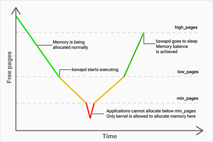
Figure : CPU usage vs. performance using Kswapd
Watermark
A watermark is a threshold or limit set on memory parameters that helps regulate the allocation and usage of system memory. Table : Watermark parameters| Parameter | Description |
|---|---|
/proc/sys/vm/min_free_kbytes |
|
/proc/sys/vm/watermark_scale_factor |
|
/proc/sys/vm/watermark_boost_factor |
|
Memory carveout
Memory carveouts refer to specific memory regions that the kernel can’t address, known as no-map regions. Specific subsystems such as modem, camera, aDSP, cDSP, and Qualcomm® Trusted Execution Environment (TEE)/TrustZone (TZ) use these regions exclusively and hence those are inaccessible to the Linux kernel. These carveouts are defined in the source code atarch/arm64/boot/dts/qcom/<target>.dtsi.
They fall under the reserved-memory node and can be configured.
The following code shows the no-map regions for the cDSP, camera, modem, and QTEE/TrustZone (TZ) subsystems:
0x8b800000is the base address of the modem region.0xf600000is the size of the modem region, which is 246 MB.- Add
status = disabledto make this region available for the Linux kernel.
0x1c00000) to 20 MB (0x1400000):
Before: