

Pinout
The figure below shows the default functions of the IQ-8275 EVK 40-pin LS connector.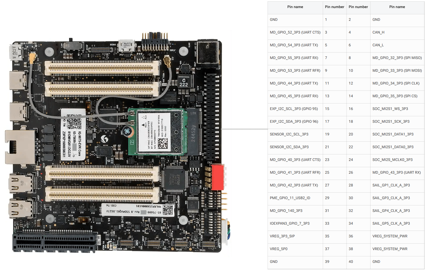
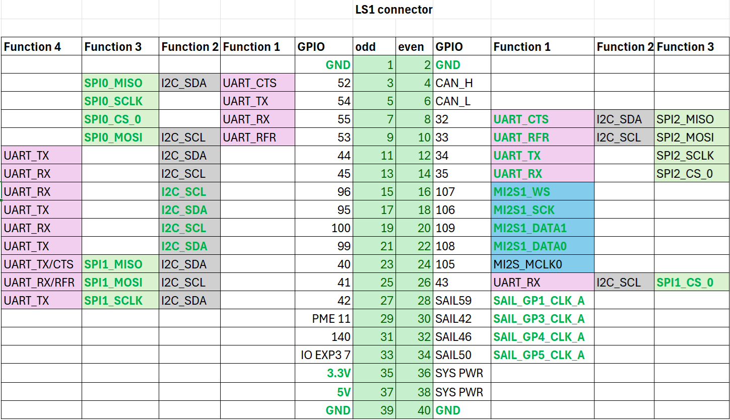
GPIOs
The following commands require root privileges. Use
sudo su to switch to the root user.Identify GPIO Subsystem Numbers
Identify the base GPIO number by running the following command and looking forplatform/f000000.pinctrl (gpiochip4).
| LS1 Connector GPIO | |||
|---|---|---|---|
| GPIO | Odd | Even | GPIO |
| GND | 1 | 2 | GND |
| 52 | 3 | 4 | CAN_H |
| 54 | 5 | 6 | CAN_L |
| 55 | 7 | 8 | 32 |
| 53 | 9 | 10 | 33 |
| 44 | 11 | 12 | 34 |
| 45 | 13 | 14 | 35 |
| 96 | 15 | 16 | 107 |
| 95 | 17 | 18 | 106 |
| 100 | 19 | 20 | 109 |
| 99 | 21 | 22 | 108 |
| 40 | 23 | 24 | 105 |
| 41 | 25 | 26 | 43 |
| 42 | 27 | 28 | SAIL59 |
| PME 11 | 29 | 30 | SAIL42 |
| 140 | 31 | 32 | SAIL46 |
| IO EXP3 7 | 33 | 34 | SAIL50 |
| 3.3V | 35 | 36 | SYS PWR |
| 5V | 37 | 38 | SYS PWR |
| GND | 39 | 40 | GND |
Configure GPIOs from User Space
Use thelibgpiod library from user space to control the GPIOs for better performance.
1
Install the Arm64 toolchain
2
Download and extract libgpiod
3
Configure the sources for static linking
4
Compile the library
Compiling creates linked binaries.
5
Build the statically linked binaries
6
Push the binaries to the device
7
List GPIO chips on the device
Run Example output:
gpiodetect to list the GPIO chips.8
Display GPIO line information
Run Example output:
gpioinfo to view the lines for a specific chip.9
Set a GPIO value
To set GPIO line Example output:
54 on gpiochip4, run:10
Read a GPIO value
To read GPIO line Example output:After reading the value, Example output:
0 on gpiochip4, run:gpioinfo shows the line returned to input mode.UART
Pins 5 and 7 are configured for UART by default (GPIO lines 54 and 55, mapping touart12 = qup1_se5 (0xa98000)).
Follow the Modify serial engine node procedure to enable the UART interface. After enabling, the device node appears at /dev/ttyHS3.
- Shell
1
Connect pins
Short pin 5 and pin 7 with a Dupont wire.
2
Configure UART
3
Open two SSH terminals
Terminal 1 (RX):
cat /dev/ttyHS3Terminal 2 (TX): echo "hello world!" > /dev/ttyHS3I2C
Pins 8 and 10 are configured for I2C by default (GPIO lines 32 and 33, mapping toi2c4 = qup0_se4 (0x990000)).
Follow the Modify serial engine node procedure to enable the I2C interface.
SPI
Pins 11 and 13 are configured for SPI by default (GPIO lines 44 and 45, mapping tospi10 = qup1_se3 (0xa8c000)).
Follow the Modify serial engine node procedure to enable the SPI interface.