

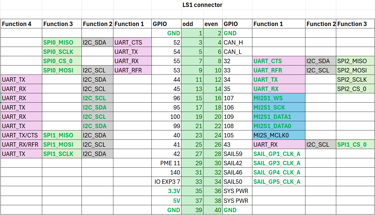
Pinout
The figure below shows the default functions of the IQ-9075 EVK 40-pin LS connector.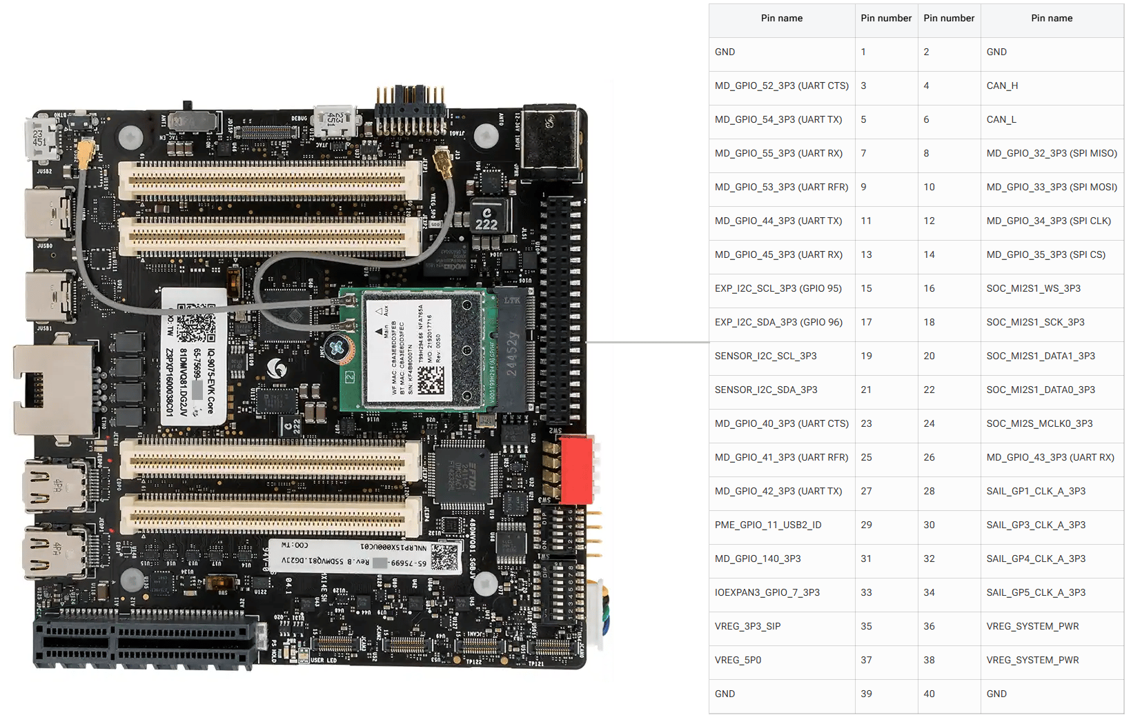
GPIOs
The following commands require root privileges. Use
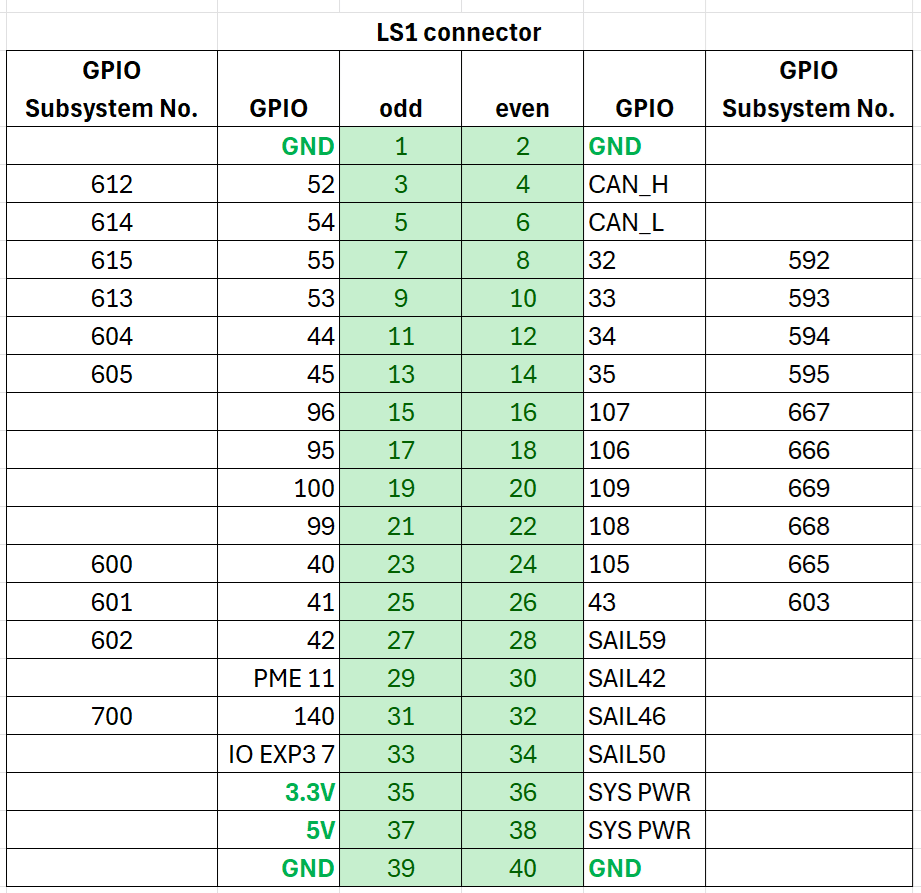
sudo su to switch to the root user.Identify GPIO Subsystem Numbers
Identify the base GPIO number by running the following command and looking forplatform/f000000.pinctrl (gpiochip4). For IQ-9075, the base is 560.
cat /sys/kernel/debug/gpio
Control GPIOs via sysfs
Configure direction and value
cd gpio614
echo out > direction
echo 1 > value
| Attribute | Values |
|---|---|
direction | in (input), out (output) |
value | 0 (low), 1 (high) |
edge | rising, falling, both, none |
GPIO Code Examples
- C
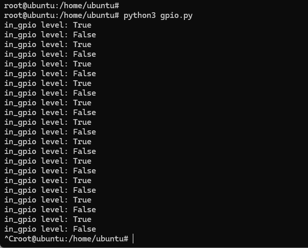
- Python
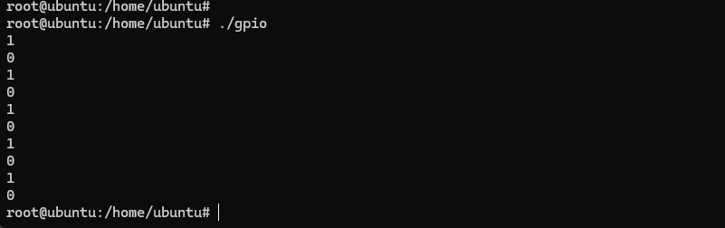
The following example sets pin 5 as output, pin 7 as input, and loops to check the level of pin 7.
#include <stdio.h>
#include <stdlib.h>
#include <unistd.h>

int out_gpio = 614;
int in_gpio = 615;

int main() {
    char export_path[50] = {};
    char export_command[100] = {};
    snprintf(export_path, sizeof(export_path), "/sys/class/gpio/export");
    snprintf(export_command, sizeof(export_command), "echo %d > %s ", out_gpio, export_path);
    system(export_command);
    snprintf(export_command, sizeof(export_command), "echo %d > %s ", in_gpio, export_path);
    system(export_command);

    char direction_path[50] = {};
    snprintf(direction_path, sizeof(direction_path), "/sys/class/gpio/gpio%d/direction", out_gpio);
    FILE *direction_file = fopen(direction_path, "w");
    if (direction_file == NULL) { perror("Failed to open GPIO direction file"); return -1; }
    fprintf(direction_file, "out");
    fclose(direction_file);

    snprintf(direction_path, sizeof(direction_path), "/sys/class/gpio/gpio%d/direction", in_gpio);
    direction_file = fopen(direction_path, "w");
    if (direction_file == NULL) { perror("Failed to open GPIO direction file"); return -1; }
    fprintf(direction_file, "in");
    fclose(direction_file);

    char value_in_path[50] = {};
    char value_out_path[50] = {};
    char cat_command[100] = {};
    snprintf(value_out_path, sizeof(value_out_path), "/sys/class/gpio/gpio%d/value", out_gpio);
    snprintf(value_in_path, sizeof(value_in_path), "/sys/class/gpio/gpio%d/value", in_gpio);
    snprintf(cat_command, sizeof(cat_command), "cat %s", value_in_path);

    FILE *value_out_file = fopen(value_out_path, "w");
    if (value_out_file == NULL) { perror("Failed to open GPIO value file"); return -1; }

    for (int i = 0; i < 5; i++) {
        fprintf(value_out_file, "1"); fflush(value_out_file);
        system(cat_command); sleep(1);
        fprintf(value_out_file, "0"); fflush(value_out_file);
        system(cat_command); sleep(1);
    }
    fclose(value_out_file);

    char unexport_path[50] = {};
    char unexport_command[100] = {};
    snprintf(unexport_path, sizeof(unexport_path), "/sys/class/gpio/unexport");
    snprintf(unexport_command, sizeof(unexport_command), "echo %d > %s ", out_gpio, unexport_path);
    system(unexport_command);
    snprintf(unexport_command, sizeof(unexport_command), "echo %d > %s ", in_gpio, unexport_path);
    system(unexport_command);
    return 0;
}
Install The following example sets pin 5 as output, pin 7 as input, and loops to check the level of pin 7.
python3-periphery:apt install python3-pip
apt install python3-periphery
from periphery import GPIO
import time

out_gpio = GPIO(614, "out")
in_gpio = GPIO(615, "in")

try:
    while True:
        try:
            out_gpio.write(True)
            print(f"in_gpio level: {in_gpio.read()}")
            out_gpio.write(False)
            print(f"in_gpio level: {in_gpio.read()}")
            time.sleep(1)
        except KeyboardInterrupt:
            out_gpio.write(False)
            break
except IOError:
    print("Error")
finally:
    out_gpio.close()
    in_gpio.close()
UART
Pins 5 and 7 are configured for UART by default (GPIO lines 54 and 55, mapping touart12 = qup1_se5 (0xa98000)).
Follow the Modify serial engine node procedure to enable the UART interface. After enabling, the device node appears at /dev/ttyHS3.
ubuntu@ubuntu:/dev$ ls -al ttyHS3
crw-rw---- 1 root dialout 236, 2 Nov 25 18:16 ttyHS3
- Shell
- C
- Python
Connect pins
Short pin 5 and pin 7 with a Dupont wire.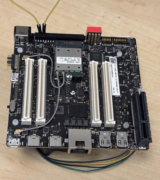
Pay attention to pin order. Do not short power and ground pins — this may damage the board.
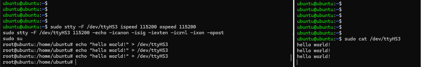
Configure UART
sudo stty -F /dev/ttyHS3 ispeed 115200 ospeed 115200
sudo stty -F /dev/ttyHS3 115200 -echo -icanon -isig -iexten -icrnl -ixon -opost
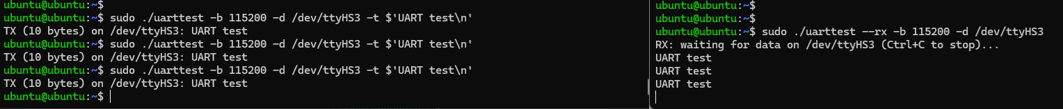
The following C program sends and receives data over UART with full raw-mode configuration and optional PM clock vote support.
#define _GNU_SOURCE
#include <errno.h>
#include <fcntl.h>
#include <getopt.h>
#include <poll.h>
#include <signal.h>
#include <stdio.h>
#include <stdlib.h>
#include <string.h>
#include <termios.h>
#include <unistd.h>
#include <sys/ioctl.h>

#ifndef TIOCPMGET
#define TIOCPMGET  0x544D
#endif
#ifndef TIOCPMPUT
#define TIOCPMPUT  0x544E
#endif

static volatile sig_atomic_t g_stop = 0;
static void on_sigint(int sig) { (void)sig; g_stop = 1; }

static speed_t baud_to_speed(int baud) {
    switch (baud) {
        case 9600:   return B9600;
        case 19200:  return B19200;
        case 38400:  return B38400;
        case 57600:  return B57600;
        case 115200: return B115200;
        case 230400: return B230400;
        default:     return 0;
    }
}

static void uart_clock_vote_on(int fd) {
    if (ioctl(fd, TIOCPMGET, 0) < 0 && errno != ENOTTY)
        fprintf(stderr, "WARN: ioctl(TIOCPMGET) failed: %s\n", strerror(errno));
}

static void uart_clock_vote_off(int fd) {
    if (ioctl(fd, TIOCPMPUT, 0) < 0 && errno != ENOTTY)
        fprintf(stderr, "WARN: ioctl(TIOCPMPUT) failed: %s\n", strerror(errno));
}

static int configure_serial(int fd, int baud, int rx_block_forever) {
    struct termios tty;
    if (tcgetattr(fd, &tty) != 0) { perror("tcgetattr"); return -1; }
    cfmakeraw(&tty);
    speed_t spd = baud_to_speed(baud);
    if (spd == 0) { fprintf(stderr, "Unsupported baud rate: %d\n", baud); return -1; }
    cfsetispeed(&tty, spd); cfsetospeed(&tty, spd);
    tty.c_cflag &= ~(PARENB | CSTOPB | CSIZE); tty.c_cflag |= CS8 | CLOCAL | CREAD | ~CRTSCTS;
    tty.c_iflag &= ~(IXON | IXOFF | IXANY);
    tty.c_cc[VMIN]  = rx_block_forever ? 1 : 0;
    tty.c_cc[VTIME] = 0;
    if (tcsetattr(fd, TCSANOW, &tty) != 0) { perror("tcsetattr"); return -1; }
    tcflush(fd, TCIOFLUSH);
    return 0;
}

int main(int argc, char **argv) {
    struct sigaction sa; memset(&sa, 0, sizeof(sa));
    sa.sa_handler = on_sigint; sigaction(SIGINT, &sa, NULL);

    const char *device = "/dev/ttyHS3";
    int baud = 115200, rx_mode = 0;
    const char *tx = "hello world!\n";

    int c;
    while ((c = getopt(argc, argv, "d:b:t:Rh")) != -1) {
        switch (c) {
            case 'd': device = optarg; break;
            case 'b': baud = atoi(optarg); break;
            case 't': tx = optarg; break;
            case 'R': rx_mode = 1; break;
        }
    }

    int fd = open(device, O_RDWR | O_NOCTTY);
    if (fd < 0) { fprintf(stderr, "Failed to open %s: %s\n", device, strerror(errno)); return 1; }
    if (configure_serial(fd, baud, rx_mode) != 0) { close(fd); return 1; }

    if (rx_mode) {
        struct pollfd pfd = { .fd = fd, .events = POLLIN };
        uart_clock_vote_on(fd);
        printf("RX: waiting on %s (Ctrl+C to stop)...\n", device);
        while (!g_stop) {
            if (poll(&pfd, 1, -1) < 0) { if (errno == EINTR) continue; break; }
            if (pfd.revents & POLLIN) {
                unsigned char buf[512];
                ssize_t r = read(fd, buf, sizeof(buf));
                if (r > 0) { fwrite(buf, 1, r, stdout); fflush(stdout); }
            }
        }
        uart_clock_vote_off(fd);
    } else {
        uart_clock_vote_on(fd);
        ssize_t w = write(fd, tx, strlen(tx));
        printf("TX (%zd bytes) on %s: %s", w, device, tx);
        uart_clock_vote_off(fd);
    }
    close(fd);
    return 0;
}
The following Python script sends and receives data over UART using raw termios configuration.
#!/usr/bin/env python3
import argparse, errno, fcntl, os, select, signal, sys, termios

TIOCPMGET = 0x544D
TIOCPMPUT = 0x544E
STOP = False

def sigint_handler(signum, frame):
    global STOP
    STOP = True

signal.signal(signal.SIGINT, sigint_handler)

def vote_clock_on(fd):
    try: fcntl.ioctl(fd, TIOCPMGET, 0)
    except OSError as e:
        if e.errno != errno.ENOTTY: print(f"WARN: {e}", file=sys.stderr)

def vote_clock_off(fd):
    try: fcntl.ioctl(fd, TIOCPMPUT, 0)
    except OSError as e:
        if e.errno != errno.ENOTTY: print(f"WARN: {e}", file=sys.stderr)

def set_raw_8n1(fd, baud, rx_block_forever):
    attrs = termios.tcgetattr(fd)
    iflag, oflag, cflag, lflag, ispeed, ospeed, cc = attrs
    iflag &= ~(termios.IGNBRK | termios.BRKINT | termios.PARMRK | termios.ISTRIP |
               termios.INLCR | termios.IGNCR | termios.ICRNL | termios.IXON | termios.IXOFF | termios.IXANY)
    oflag &= ~termios.OPOST
    lflag &= ~(termios.ECHO | termios.ECHONL | termios.ICANON | termios.ISIG | termios.IEXTEN)
    cflag &= ~(termios.CSIZE | termios.PARENB | termios.CSTOPB)
    cflag |= termios.CS8 | termios.CREAD | termios.CLOCAL
    if hasattr(termios, "CRTSCTS"): cflag &= ~termios.CRTSCTS
    baud_map = {9600: termios.B9600, 19200: termios.B19200, 38400: termios.B38400,
                57600: termios.B57600, 115200: termios.B115200, 230400: termios.B230400}
    if baud not in baud_map: raise ValueError(f"Unsupported baud rate: {baud}")
    ispeed = ospeed = baud_map[baud]
    cc[termios.VMIN] = 1 if rx_block_forever else 0
    cc[termios.VTIME] = 0
    termios.tcsetattr(fd, termios.TCSANOW, [iflag, oflag, cflag, lflag, ispeed, ospeed, cc])
    termios.tcflush(fd, termios.TCIOFLUSH)

def rx_forever(fd, device):
    vote_clock_on(fd)
    print(f"RX: waiting on {device} (Ctrl+C to stop)...")
    while not STOP:
        rlist, _, _ = select.select([fd], [], [], 1.0)
        if rlist:
            data = os.read(fd, 512)
            if data: sys.stdout.buffer.write(data); sys.stdout.buffer.flush()
    vote_clock_off(fd)
    print("\nRX: stopped.")

def tx_once(fd, device, payload):
    vote_clock_on(fd)
    n = os.write(fd, payload)
    sys.stdout.write(f"TX ({n} bytes) on {device}: ")
    sys.stdout.buffer.write(payload); sys.stdout.buffer.flush()
    vote_clock_off(fd)

def main():
    p = argparse.ArgumentParser()
    p.add_argument("-d", "--device", default="/dev/ttyHS3")
    p.add_argument("-b", "--baud", type=int, default=115200)
    p.add_argument("-t", "--tx", default="hello world!\n")
    p.add_argument("-R", "--rx", action="store_true")
    args = p.parse_args()
    fd = os.open(args.device, os.O_RDWR | os.O_NOCTTY)
    set_raw_8n1(fd, args.baud, rx_block_forever=args.rx)
    if args.rx: rx_forever(fd, args.device)
    else: tx_once(fd, args.device, args.tx.encode("utf-8", errors="replace"))
    os.close(fd)

if __name__ == "__main__":
    raise SystemExit(main())

I2C
I2C (Inter-Integrated Circuit) is a bidirectional 2-wire bus for inter-IC control. Every device on the bus has a unique address. The I2C core supports multi-controller mode, 10-bit target addressing, and 10-bit extendable addressing. Pins 8 and 10 are configured for I2C by default (GPIO lines 32 and 33, mapping toi2c4 = qup0_se4 (0x990000)).
Follow the Modify serial engine node procedure to enable the I2C interface. After enabling, verify the device nodes:
ls /dev/i2c*
# Expected: /dev/i2c-18  /dev/i2c-19  /dev/i2c-20  /dev/i2c-21  /dev/i2c-22  /dev/i2c-23  /dev/i2c-24  /dev/i2c-25
- Shell
- C
- Python
The following example writes
0xaa to address 0x01 of a device at I2C address 0x38.#include <stdio.h>
#include <stdlib.h>
#include <stdint.h>
#include <fcntl.h>
#include <unistd.h>
#include <linux/i2c-dev.h>
#include <sys/ioctl.h>
#define I2C_DEVICE_PATH "/dev/i2c-1"
int main() {
uint8_t data[2] = {0x01, 0xaa};
int i2c_file;
if ((i2c_file = open(I2C_DEVICE_PATH, O_RDWR)) < 0) {
perror("Failed to open I2C device");
return -1;
}
ioctl(i2c_file, I2C_TENBIT, 0);
ioctl(i2c_file, I2C_RETRIES, 5);
printf("i2cdetect addr: ");
for (int x = 0; x < 0x7f; x++) {
if (ioctl(i2c_file, I2C_SLAVE, x) < 0) {
perror("Failed to set I2C slave address");
close(i2c_file);
return -1;
}
if (write(i2c_file, data, 2) == 2)
printf("0x%x,", x);
}
close(i2c_file);
printf("\r\n");
return 0;
}
Install The following example writes Connect sensor to pins 11 and 13, then run:
python3-smbus:sudo apt install python3-smbus
0xaa to address 0x01 of a device at I2C address 0x38.import smbus
def main():
data = [0x01, 0xaa]
i2c_bus = None
try:
i2c_bus = smbus.SMBus(1)
print("i2cdetect addr: ", end="")
for address in range(0x7F):
try:
i2c_bus.write_i2c_block_data(address, 0, data)
print("0x{:02X},".format(address), end="")
except OSError:
pass
print()
except Exception as e:
print(f"An error occurred: {e}")
finally:
if i2c_bus:
i2c_bus.close()
if __name__ == "__main__":
main()
python3 i2c.py
SPI
SPI (Serial Peripheral Interface) is a synchronous full-duplex 4-wire serial bus. Pins 11 and 13 are configured for SPI by default (GPIO lines 44 and 45, mapping tospi10 = qup1_se3 (0xa8c000)).
Follow the Modify serial engine node procedure to enable the SPI interface.
- C
- Python
The following example sends and receives data over SPI with loopback.
#include <stdio.h>
#include <stdlib.h>
#include <stdint.h>
#include <fcntl.h>
#include <unistd.h>
#include <linux/spi/spidev.h>
#include <sys/ioctl.h>

#define SPI_DEVICE_PATH "/dev/spidev12.0"

int main() {
    int spi_file;
    uint8_t tx_buffer[50] = "hello world!";
    uint8_t rx_buffer[50];

    if ((spi_file = open(SPI_DEVICE_PATH, O_RDWR)) < 0) {
        perror("Failed to open SPI device");
        return -1;
    }

    uint8_t mode = SPI_MODE_0, bits = 8;
    ioctl(spi_file, SPI_IOC_WR_MODE, &mode);
    ioctl(spi_file, SPI_IOC_WR_BITS_PER_WORD, &bits);

    struct spi_ioc_transfer transfer = {
        .tx_buf = (unsigned long)tx_buffer,
        .rx_buf = (unsigned long)rx_buffer,
        .len = sizeof(tx_buffer),
        .speed_hz = 1000000,
        .bits_per_word = 8,
    };

    if (ioctl(spi_file, SPI_IOC_MESSAGE(1), &transfer) < 0) {
        perror("Failed to perform SPI transfer");
        close(spi_file);
        return -1;
    }

    printf("tx_buffer:\n %s\n", tx_buffer);
    printf("rx_buffer:\n %s\n", rx_buffer);
    close(spi_file);
    return 0;
}
Install
python3-spidev:sudo apt install python3-spidev
import spidev

def main():
    tx_buffer = [ord(c) for c in "hello world!"]
    try:
        spi = spidev.SpiDev()
        spi.open(12, 0)
        spi.max_speed_hz = 1000000
        rx_buffer = spi.xfer2(tx_buffer[:])
        print("tx_buffer:\n", ''.join(map(chr, tx_buffer)))
        print("rx_buffer:\n", ''.join(map(chr, rx_buffer)))
    except Exception as e:
        print(f"An error occurred: {e}")
    finally:
        spi.close()

if __name__ == "__main__":
    main()