

- The CAN bus provides one point of entry to communicate with all network nodes enabling central data logging and diagnostics purposes.
- CAN frames are prioritized by message ID. So that the high priority message ID gets control of the bus arbitration. Bitwise arbitration helps manage CAN bus access and avoid collisions through ID-based priority.
- The CAN bus has two logical states during operation:
- Recessive level, where the recessive bus state is equivalent to logical high and called as the Idle state.
- Dominant level, where the dominant bus state is equivalent to logical low.
- Any node can transmit data at any time. There is no primary-secondary node concept in case of CAN communication.
- CAN nodes are synchronized using bit-synchronization where each bit time is divided into four segments of time quanta.
- The CAN protocol ensures error handling and detecting CAN errors including CRC and ACK.
CAN features
The CAN protocol supports the following features:- Priority-based bus access.
- Nondestructive bitwise-based arbitration.
- Broadcast through all-frame transfer.
- Multicast frame transfer by acceptance filtering.
- Error detection and error signaling.
- Automatic deactivation of faulty nodes by identifying the failure nodes.
- DMA mode: CAN frames are moved from RX FIFO to system memory through DMA with minimal CPU load.
- Polling mode: CPU periodically checks RX FIFO for new frames and processes them.
- Interrupt mode: When a frame is received, the CPU is notified using an interrupt and it reads the data from the RX FIFO.
CAN interface supports the following baud rate range for each channel:
CAN architecture
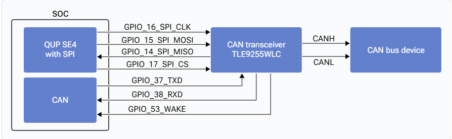
The CAN IP is part of the SoC and it’s a configurable CAN controller. TLE9255WLC is an external transceiver and can be configured through the SPI interface, which works with 4 MHz clock frequency having SPI mode 1. The SoC controller is connected to a QUP block with SE4 configured by a 4-pin SPI operation.- IQ-9075
- IQ-8275
CAN0The Dragonwing IQ-9075 EVK supports eight CAN channels. The Dragonwing IQ-9075 EVK supports the CAN0 connection with the TLE9255WLC transceiver. The following figure shows connection between the CAN0 channels and the TLE9255WLC transceiver that supports the baud rate up to 5 MBPS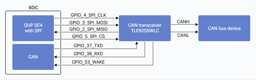

CAN files
The following are the CAN interface files:Verify CAN interface
For information about verifying the CAN interface, see CAN test commands.Customize CAN interface
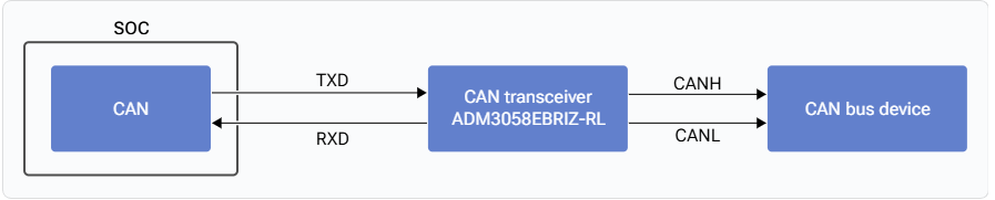
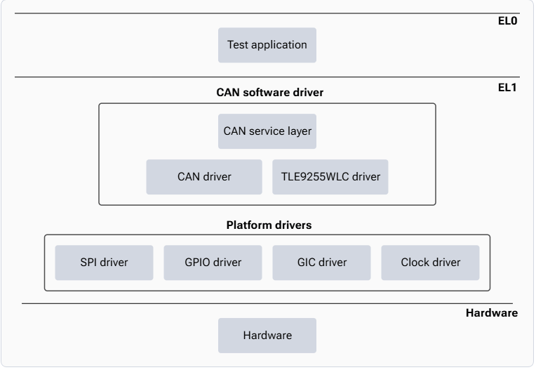
Qualcomm recommends using the default CAN transceiver (TLE9255WLC). When the default transceiver is used, software changes aren’t required as the platform CAN software stack provides full support. If a dummy transceiver (for example, ADM3058EBRIZ) is used, CAN driver changes aren’t required, as all transceiver handling is managed in hardware. However, if a new or different CAN transceiver is introduced, the corresponding transceiver driver must be integrated and configured in the software. The following sections describe the required changes, using TLE9255 as an example. Map transceiver to platform CAN driver The new transceiver must be mapped in the platform CAN driver configuration atsail_proc/BSP/can/src/sailel1/Can_Plt_Cfg.c.
Example (Dragonwing IQ-8275 EVK):
- Add a mapping array for the new transceiver:
- Map the appropriate CAN channel (example for CAN0):
sail_proc/BSP/cantrcv_tle9255/src/sailel1/cantrcv_Task.c
This driver handles transceiver‑specific operations such as initialization, mode control, and fault handling.
Initialize transceiver driver
The new transceiver driver must be initialized during system startup.
File: sail_proc/BSP/el_entry/src/sailsw1/sailel1_main.c
Add the initialization call for the new transceiver driver.
Example: