

NoteRTSS is applicable to Qualcomm DragonwingTM IQ-9075 and Qualcomm Dragonwing IQ-8275.
RTSS boot flow
The RTSS boots up in parallel with the APSS boot flow. The following figure shows the sequence of tasks at different levels in the RTSS bootup process: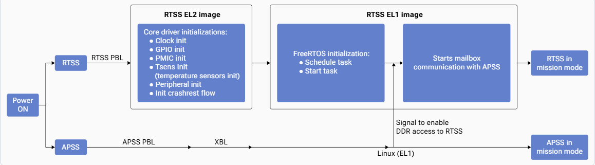
- Reset state exit: The boot core exits the reset state and begins executing the RTSS PBL. The APSS PBL simultaneously exits the reset state and begins execution. For more details, see APSS cold boot flow.
- PBL execution:
- Initializes the phase-locked loops (PLLs) and clocks.
- Loads and authenticates the RTSS image (boot code in the EL2 layer and FreeRTOS in the EL1 layer).
- Jumps to the RTSS EL2.
- EL2 image initialization:
- Initializes core drivers such as clock, GPIO, temperature monitoring, voltage monitoring, UART, and I2C.
- Initializes crash dump collection.
- Hands over control to RTSS EL1.
- EL1 image initialization:
- Completes FreeRTOS initialization to schedule and start tasks.
- Initializes dedicated peripherals such as QUP (I2C, SPI, and UART).
- Shares DDR memory between the APSS and RTSS. Ensure that the mailbox software drivers on both APSS and RTSS use the dedicated DDR shared memory space for communication between APSS and RTSS.