
Prerequisites
- Set up debug UART.
- Go to UART terminal.
- To enable logging on to UART terminal, do the following:
- Select Enter in the UART Shell to access
sail_proc@home$. The following sample output show the logs that verify the access tosail_proc@home$. - Run
setlog <Level > <Privilege>on the UART terminal to set the allowed logging based on level and privilege. Parameters:<Level>: info, err, warn, or dbg<Privilege>: el1 or el2
The following sample output shows the logs for loglevel set to LOG_INFO: c0[ 208.449904s]CPU 0 -: setlog info el1
c0[ 208.450087s]>>>>>> EL1 UART loglevel set to LOG_INFO Success <<<<<<<
c0[ 208.450153s]Please use help or exit command….
c0[ 208.450190s]sail_proc@home$
- Select Enter in the UART Shell to access
Procedure
Run the following commands and verify the logs to validate the successful execution of commands:helpi2cel1spigpt
help
Runhelp on the UART terminal to know about the list of supported commands and their usage.
For example,
The following sample logs show the usage references and command references:
i2cel1
Runi2cel1 on the UART terminal to do the I2C functional test.
Parameters: None For example,NoteThei2cel1test command is for i2c0 only. For i2c1, you must update the test application.NotePMIC is connected to I2C.
The following sample logs show the successful validation of the
i2cel1 command:
NoteTo get all the I2C test result logs, enable the INFO log level by running the following command:
spi
Runspi on the UART terminal to do the SPI functional test.
Parameters: None
For example,
The following sample logs show the successful validation of the
spi command:
Note
TC_SPI_002/TC_SPI_003/TC_SPI_005 are expected to fail due to no device ID and scratch register. These test cases will be removed in a future release.Note
gpt
Rungpt <subcommand> <value> on the UART terminal to do the GPT functional test.
Parameters:
The following are the various gpt commands:
<subcommand>: start, stop, or stats<value>: Value can be any number.
gpt start <value>For example,The following sample logs show the initialization of the timer test:
gpt stopFor example,The following sample logs show the termination of the timer test:gpt statsFor example,The following sample logs show the statistics for various GPT channels:
CAN
Run the followingcan commands on the UART terminal to do the CAN functional test:
can initcan TXcan RX
Run CAN test commands
-
can initSyntax:Sample logs forcan -t 0 -config 1: -
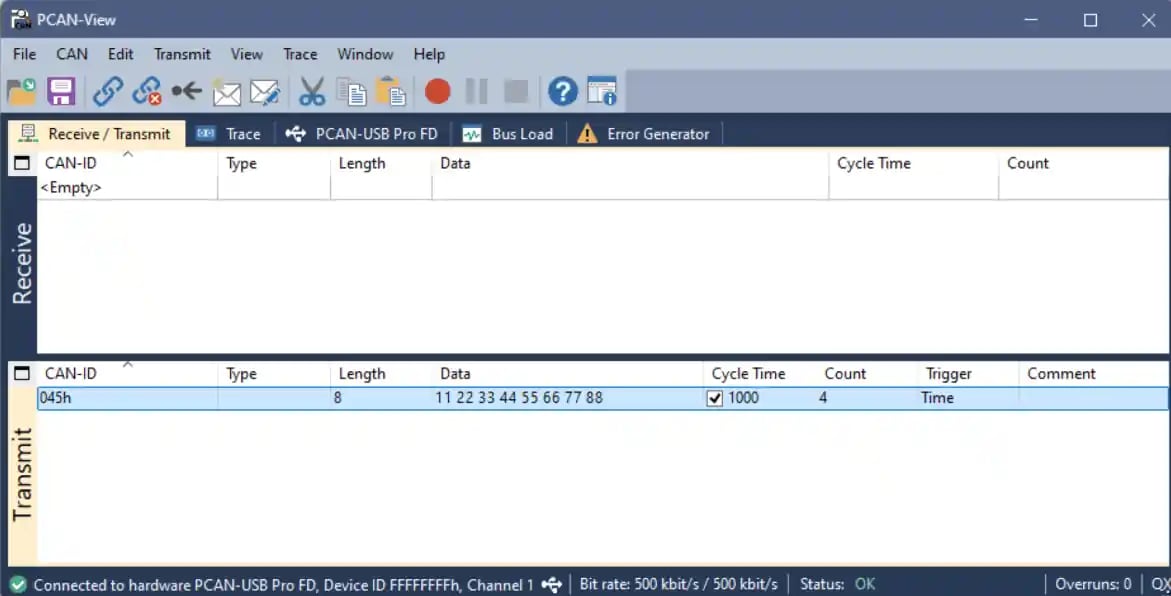
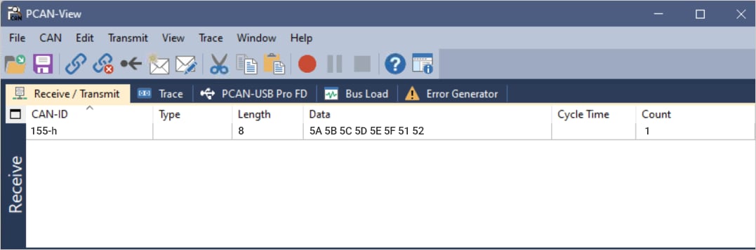
can TX - standard IDSyntax:Parameters:x= CAN controller ID: 0 to 7 Sample logs forcan -t 3 -c xThe CAN TX data shows up on the PCAN-View application.
can TX - FD ID
Syntax:
x = CAN controller ID: 0 to 7
Sample logs for can -t 5 -c x
CAN RX
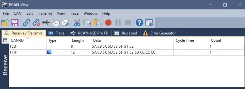
To run the CAN RX command, do the following:
- Select Transmit > New Message ….
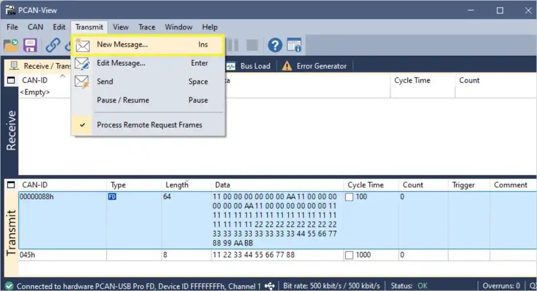
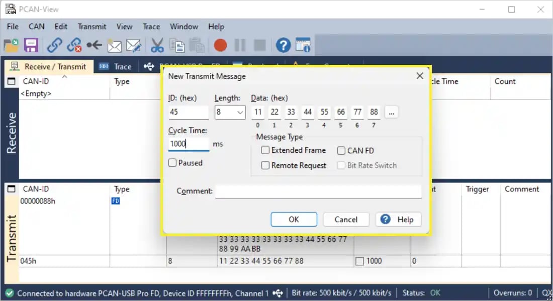
- ID: Enter the CAN ID (For example, 123).
- Length: Set the number of data bytes (8, 12, 32, 64).
- Data: Enter the data bytes (For example, 11 22 33 44 55 66 77 88).
- cycle time : 1000 ms
- under Message Type, ensure to select the CAN FD checkbox if it’s a CAN FD frame.
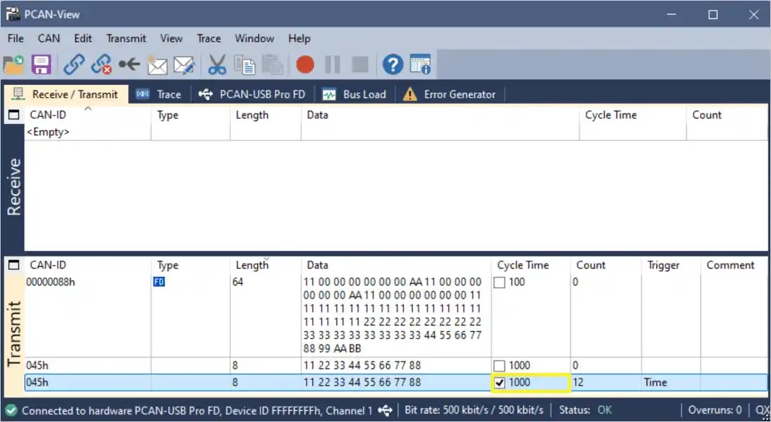
NoteTo stop sending the message, unselect the cycle time.