

- Uses CSMA/CD method and bitwise contention to sense the bus at the bit-level and transmit the message.
- Each message is assigned a priority. Messages with the highest priority always control the bus arbitration. Since arbitration is based on bits, there are dominant and recessive bit levels.
- Any node can transmit at any time, no primary-secondary nodes.
- All the data is transmitted through two (differential pair) lines: CAN_H and CAN_L line.
- CAN nodes are synchronized using bit-synchronization where each bit time is divided in to four segments of time quanta.
- Facilitates communication between multiple nodes through a message-based protocol, eliminating the need for extensive wiring.
- Ensures data security with error management including detection, signaling, and correction.
Note
- CAN is enabled by default in QCS6490 and QCS5430.
- Dragonwing IQ-9075, Dragonwing IQ-8275, and Dragonwing IQ-615 don’t support CAN.
CAN features
The CAN protocol supports the following features.- Multicontroller priority-based bus access
- Nondestructive content-based arbitration
- Broadcast through all-frame transfer
- Multicast frame transfer by acceptance filtering
- Remote data request
- Configuration flexibility
- Network-wide data consistency
- Error detection and error signaling
- Automatically retransmits frames that lose arbitration, lack acknowledgment, or encounter errors during transmission
- Identifies differences between temporary node errors and permanent node failures, and the automatic deactivation of faulty nodes
CAN architecture
The MCP2517 is an external configurable CAN controller, which can be accessed through the SPI line. The SPI interface supports up to 20 MHz with support for Mode0,1. The controller is connected to a QUP block with SE3 configured by a 4-pin SPI operation. The SPI controller is connected to a transceiver (MCP2561xxx) which connects to the CAN bus. Power input to the SPI controller and the CAN transceiver is through the SoC.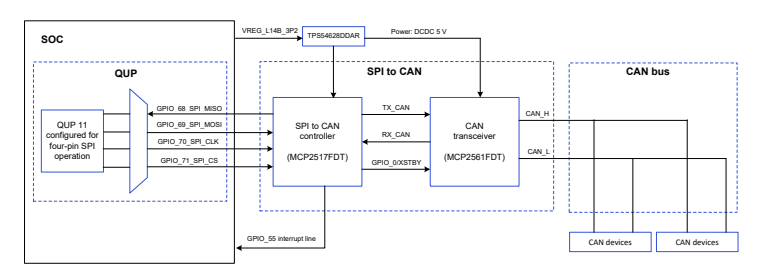
Figure : CAN architecture
The user application communicates with the network interface provided by the SocketCAN. The software driver is a client of the SPI core module in Linux, to which the QUP_SPI driver is registered with. The actual hardware is connected through the SPI pins.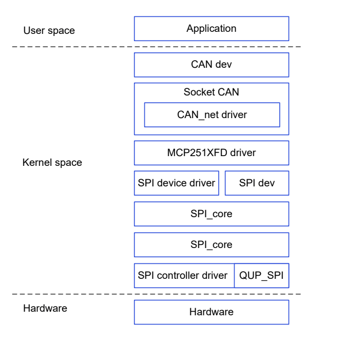
Figure : CAN software stack
CAN APIs
For CAN public APIs, see https://www.kernel.org/doc/Documentation/networking/can.txt.CAN samples and tools
The SocketCAN user space utilities and tools to display, record, generate, and replay the CAN traffic are listed in the following table. Table : SocketCAN utilities| Utility | Description |
|---|---|
candump | To display, filter and log CAN data to files. |
canplayer | To replay CAN log files. |
cansend | To send a single frame. |
cangen | To generate (random) CAN traffic. |
cansniffer | To display CAN data content differences (just 11‑bit CAN IDs). |
kernel/drivers/net/can/spi/mcp251xfd/mcp251xfd-core.c.
CAN analyzer - PCAN-USB FD
The PCAN-USB FD is a versatile CAN packet/message sniffer that can operate as a node on any CAN bus, supporting flexible data rates. It can be used to sniff and send CAN packets on a host machine over USB. The key features are as follows:- PCAN-View GUI tool
- Provides easy ways to sniff and send CAN packets as per-user needs.
- Monitors and debugs CAN packets during development and testing.
- PCAN-USB FD interface
- Enables a simple connection to CAN FD and CAN networks.
- Compact plastic casing suitable for mobile applications.
- Galvanic isolation of up to 500 V decouples the PC from the CAN bus.
- CAN FD standard
- Characterized by higher bandwidth for data transfer.
- Allows transmission of up to 64 data bytes per CAN FD frame (instead of 8).
- Supports bit rates up to 12 Mbit/s.
- Downward compatible with the CAN 2.0 standard.
- CAN FD nodes can be inserted into existing CAN networks without CAN FD extensions.
- Connect to the DB9 connector.
- The PCAN has a DB9 connector on which any standard DB9 connector can be plugged in.
- Connect to the Qualcomm device.
- Pull out the CAN_H, CAN_L, and GND lines.
- Connect these lines to the two terminal-resistors of 120 Ω.
- Connect CAN_H, CAN_L, and Ground.
Figure : CAN connections
- Connect an external terminating resistor.
NoteThe device doesn’t have an internal terminating resistor of 120 Ω. This is crucial because some tools provide built-in support for the terminating resistor.
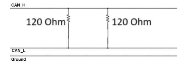
Figure : CAN terminating resistor
The following figure shows the connected hardware.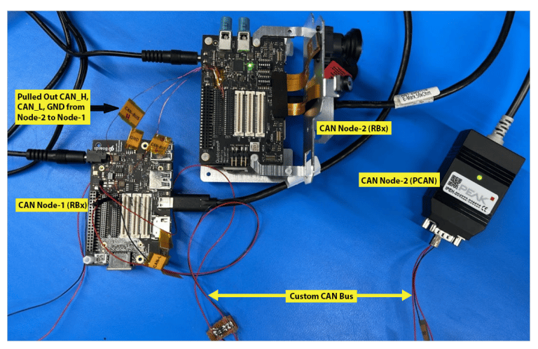
Figure : CAN USB FD, external resistor, and device connection
Bringup CAN interface
After the CAN driver is built and loaded into the kernel, the following sequence of commands sends data to identify if the CAN node is up. A CAN node can be started or stopped using the commands listed in the following table.NoteAll the network devices use
ifconfig -a.| Instruction | Command |
|---|---|
| Check for the can node number | ifconfig -a |
| Set a bit rate of 125 kbps | ip link set can0 up type can bitrate 125000 |
| Start CAN | ip link set can0 up |
| Stop CAN | ip link set can0 down |
| Check the CAN configuration | ip -details link show can0 |
| CAN internal loopback | ip link set can0 up type can bitrate 500000 loopback on |
| CAN FD internal loopback | ip link set can0 up type can bitrate 1000000 dbitrate 5000000 fd on loopback on |
| Send CAN FD frame | cansend can0 213##311223344 |
Send and receive data
Some utilities are available in theCAN-Utils file. SocketCAN enables CAN nodes for sending and receiving data. SocketCAN APIs are also used for custom applications.
- Send data with 11‑bit ID
- Send data with 29‑bit ID
- View the current incoming data on can0 node
Configure CAN interface
SocketCAN is an implementation of the CAN protocol for Linux. SocketCAN uses the Berkeley socket API, the Linux network stack and implements the CAN device drivers as network interfaces. The CAN socket API has been designed as similar as possible to the TCP/IP protocols to allow users, familiar with network programming, easily learn how to use CAN sockets.Initialize hardware
The driver initializes and configures the underlying hardware block. The initialization occurs after thedriver's _probe() function is called.
Debug CAN issues
CAN issues can be debugged using theftrace tool. The MCP2517 driver supports the dev_coredump() API.