Before you begin, set up your infrastructure as described in the Qualcomm Linux Build Guide. Interface workflow

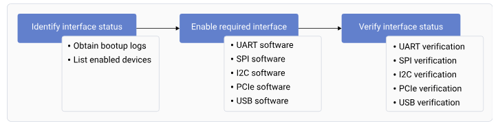
Figure : Interface workflow

Identify the interface status

The default interface status indicates the status of the interfaces during bootup. To identify the interface status, successfully register the interfaces and obtain the list of enabled interfaces.

Obtain the bootup logs

To obtain the bootup logs of the device, do the following:
  1. Open the SSH shell in permissive mode or use the ADB shell. For more information about how to run SSH, see the Use SSH section.
  2. Obtain the logs of the enabled interfaces by running the following command.
    dmesg
    
    Output:
     
    [    0.434365] msm_serial: driver initialized
    [    0.799123] 994000.serial: ttyMSM0 at MMIO 0x994000 (irq = 139, base_baud = 0) is a MSM
    [    0.801937] 99c000.serial: ttyHS1 at MMIO 0x99c000 (irq = 140, base_baud = 0) is a MSM
    [    0.804563] serial serial0: tty port ttyHS1 registered
     
    [ 0.720945] usbhub_rest_vreg GPIO handle specifies active low - ignored
    [    0.815241] dwc3-qcom 8c00000.usb: Adding to iommu group 4
    [    5.195974] dwc3-qcom a600000.usb: Adding to iommu group 18
    [    5.229464] qcom_pmic_glink pmic-glink: Failed to create device link (0x180) with a600000.usb
    [    6.195825] usb usb2: We don't know the algorithms for LPM for this host, disabling LPM.
    [    6.450338] usb 1-1: new high-speed USB device number 2 using xhci_hcd
    [    6.664583] usbcore: registered new device driver onboard-usb-hub
    [    6.730998] usb 2-1: new SuperSpeed USB device number 2 using xhci_hcd
    [    7.083668] usb 2-1.1: new SuperSpeed USB device number 3 using xhci_hcd
    [    7.217287] ax88179_178a 2-1.1:1.0 eth0: register 'ax88179_178a' at usb-0001:04:00.0-1.1, ASIX AX88179 USB 3.0 Gigabit Ethernet, 02:fe:ee:05:44:23
    [    7.217415] usbcore: registered new interface driver ax88179_178a
    [   10.223140] dwc3-qcom a600000.usb: request 0000000000000000 was not queued to ep0ou
    
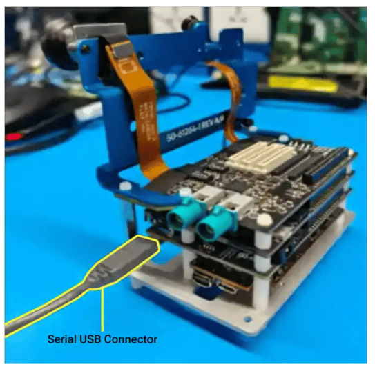
  3. Connect the UART serial port to log in to the console. USB Connector

List enabled interfaces on devices

To obtain the list of the enabled interfaces, do the following:
  • For UART, run the following command.
    ls /dev/tty*
    
    Output:
    /dev/tty    /dev/tty21 /dev/tty35  /dev/tty49  /dev/tty62   /dev/ttyp4
    /dev/tty0   /dev/tty22 /dev/tty36  /dev/tty5   /dev/tty63   /dev/ttyp5
    /dev/tty1   /dev/tty23 /dev/tty37  /dev/tty50  /dev/tty7    /dev/ttyp6
    /dev/tty10  /dev/tty24 /dev/tty38  /dev/tty51  /dev/tty8    /dev/ttyp7
    /dev/tty11  /dev/tty25 /dev/tty39  /dev/tty52  /dev/tty9    /dev/ttyp8
    /dev/tty12  /dev/tty26 /dev/tty4   /dev/tty53  /dev/ttyMSM0 /dev/ttyp9
    /dev/tty13  /dev/tty27 /dev/tty40  /dev/tty54  /dev/ttyS0   /dev/ttypa
    /dev/tty14  /dev/tty28 /dev/tty41  /dev/tty55  /dev/ttyS1   /dev/ttypb
    /dev/tty15  /dev/tty29 /dev/tty42  /dev/tty56  /dev/ttyS2   /dev/ttypc
    /dev/tty16  /dev/tty3  /dev/tty43  /dev/tty57  /dev/ttyS3   /dev/ttypd
    /dev/tty17  /dev/tty30 /dev/tty44  /dev/tty58  /dev/ttynull /dev/ttype
    /dev/tty18  /dev/tty31 /dev/tty45  /dev/tty59  /dev/ttyp0   /dev/ttypf
    /dev/tty19  /dev/tty32 /dev/tty46  /dev/tty6   /dev/ttyp1
    /dev/tty2   /dev/tty33 /dev/tty47  /dev/tty60  /dev/ttyp2
    /dev/tty20  /dev/tty34 /dev/tty48  /dev/tty61  /dev/ttyp3
    
  • For I2C, run the following command.
    ls /dev/i2c*
    
    The following output is displayed.
    /dev/i2c-0  /dev/i2c-1 /dev/i2c-16
    
  • By default, SPI isn’t enabled. To enable SPI, see SPI software device tree configuration. To verify if SPI is enabled, run the following command.
    ls /dev/spi*
    
    The following output is displayed.
    spidev14.0
    
  • For PCIe, obtain the enumeration log. For more information about PCIe probe logs, see PCIe-related configurations and QPS615 switch support.

Load QUP v3 serial engine firmware using Linux kernel

This document explains the QUP v3 serial engine firmware loading mechanism using the Linux kernel. It describes the transition from a TrustZone-based architecture—which had fixed protocol assignments and limited flexibility—to a Linux-based approach that enables dynamic protocol assignment, easier debugging, and simplified development through device tree configuration. QUP v3 contains multiple serial engines that can be configured as follows:
  • I2C
  • SPI
  • UART

Default configuration

The default configuration for each serial engine, including the selected mode of data transmission and ownership, is in the _/TZ.XF.5.0/core.tz/2.0/settings/buses/qup\_accesscontrol/qupv3/config/lemans/QUPAC\_Access.c_ file. In the default configuration, Linux owns all the serial engines.
const QUPv3_se_security_permissions_type qupv3_perms_default =
{
  /*   PeriphID,         ProtocolID,               Mode,      NsOwner,         bAllowFifo, bLoad, bModExcl  */
  /*QUPV3_0_SE0*/
  /*QUPV3_0_SE1*/
  /*QUPV3_0_SE2*/
  { QUPV3_0_SE3, QUPV3_PROTOCOL_UART_4W,   QUPV3_MODE_FIFO,   AC_HLOS,            TRUE,  TRUE, FALSE }, // BT UART (2nd Hastings)
  { QUPV3_0_SE4, QUPV3_PROTOCOL_UART_2W,   QUPV3_MODE_FIFO,   AC_HLOS,            TRUE,  TRUE, FALSE }, // VIP UART/SPI (SOC SLAVE)
  /*QUPV3_0_SE5*/                                                                                       // Spare
  { QUPV3_1_SE0, QUPV3_PROTOCOL_I2C,       QUPV3_MODE_FIFO,   AC_HLOS,            TRUE,  TRUE, FALSE }, // I2C Carplay
  /*QUPV3_1_SE1*/
  { QUPV3_1_SE2, QUPV3_PROTOCOL_UART_2W,   QUPV3_MODE_FIFO,   AC_HLOS,            TRUE,  TRUE, FALSE }, // Tuner
  { QUPV3_1_SE3, QUPV3_PROTOCOL_UART_2W,   QUPV3_MODE_FIFO,   AC_HLOS,            TRUE, FALSE, FALSE }, // Debug UART
  { QUPV3_1_SE4, QUPV3_PROTOCOL_I2C,       QUPV3_MODE_FIFO,   AC_HLOS,            TRUE,  TRUE, FALSE }, // I2C A2B Controller & Audio port expander
  { QUPV3_1_SE5, QUPV3_PROTOCOL_UART_2W,   QUPV3_MODE_FIFO,   AC_HLOS,            TRUE,  TRUE, FALSE }, // GNSS
  /*QUPV3_1_SE6*/
  { QUPV3_2_SE0, QUPV3_PROTOCOL_SPI,       QUPV3_MODE_FIFO,   AC_HLOS,            TRUE,  TRUE, FALSE }, // FPGA
  { QUPV3_2_SE1, QUPV3_PROTOCOL_I2C,       QUPV3_MODE_FIFO,   AC_HLOS,            TRUE,  TRUE, FALSE }, // PCIe I2C MUX
  { QUPV3_2_SE2, QUPV3_PROTOCOL_SPI,       QUPV3_MODE_FIFO,   AC_HLOS,            TRUE,  TRUE, FALSE }, // SPI - Audio
  { QUPV3_2_SE3, QUPV3_PROTOCOL_UART_4W,   QUPV3_MODE_FIFO,   AC_HLOS,            TRUE,  TRUE, FALSE }, // BT UART
  { QUPV3_2_SE4, QUPV3_PROTOCOL_I2C,       QUPV3_MODE_FIFO,   AC_HLOS,            TRUE,  TRUE, FALSE }, // I2C Display 1
  { QUPV3_2_SE5, QUPV3_PROTOCOL_I2C,       QUPV3_MODE_FIFO,   AC_HLOS,            TRUE,  TRUE, FALSE }, // I2C Sensor
  /*QUPV3_2_SE6 */
  { QUPV3_3_SE0,  QUPV3_PROTOCOL_SPI,       QUPV3_MODE_FIFO,   AC_HLOS,           TRUE,  FALSE, FALSE }, // SPI
};

Load firmware

The firmware files are at /lib/firmware/qcom/<target-name>/qupv3fw.elf.
  1. Enable CONFIG_QUP_FW_LOAD in the following files:
    • CONFIG_QCOM_QUP_FW_LOAD=y in arch/arm64/configs/qcom_defconfig
    • CONFIG_QCOM_QUP_FW_LOAD=m in arch/arm64/configs/qcom_vm_defconfig
  2. Identify available serial engines by checking the platform device tree for serial engine nodes. Typical SE numbering: SE0, SE1, SE2, …, SE15 (varies by platform).
    grep -r "qupv3_se" arch/arm64/boot/dts/qcom/
    
    NoteYou can choose the required protocol based on your interface requirements.
    • I2C: Sensors, EEPROMs, PMICs
    • SPI: Displays, flash memory, ADCs
    • UART: Console, GPS, Bluetooth
  3. Configure device tree by adding or modifying serial engine nodes to the device tree file.
    • Sample I2C configuration:
      &qupv3_se5_i2c {
          status = "okay";
          clock-frequency = <400000>; /* 400 KHz */
          sensor@48 {
              compatible = "vendor,sensor";
              reg = <0x48>;
          };
      };
      
    • Sample SPI configuration:
      &qupv3_se6_spi {
          status = "okay";
          spi-max-frequency = <50000000>; /* 50 MHz */
          flash@0 {
              compatible = "vendor,spi-flash";
              reg = <0>;
              spi-max-frequency = <25000000>;
          };
      };
      
    • Sample UART configuration:
      &qupv3_se7_uart {
          status = "okay";
          /delete-property/ interrupts;
          interrupts-extended = <&intc GIC_SPI 608 IRQ_TYPE_LEVEL_HIGH>;
      };
      
      Optional: Enable GSI DMA for high-throughput devices.
      qcom,enable-gsi-dma;
      
  4. Switch the serial engine protocol. For example, I2C to SPI.
    1. Original I2C configuration:
      &qupv3_se5_i2c {
          status = "disabled";
      };
      &qupv3_se5_spi {
          status = "okay";
          flash@0 {
              compatible = "vendor,flash";
              reg = <0>;
          };
      };
      
    2. New configuration (SPI)
      /* Disable I2C on SE5 */
      &qupv3_se5_i2c {
          status = "disabled";
      };
      /* Enable SPI on SE5 */
      &qupv3_se5_spi {
          status = "okay";
          
          flash@0 {
              compatible = "vendor,flash";
              reg = <0>;
          };
      };
      
    NoteReboot device for changes to take effect.
For more information about the patch series, see the following resources: Table : Device tree properties
PropertyTypeDescriptionRequired
statusstringEnable/disable SE (okay/disabled)Yes
qcom,enable-gsi-dmabooleanEnable GSI DMA modeNo
clock-frequencyu32I2C clock frequency (Hz)No
spi-max-frequencyu32SPI max frequency (Hz)No
pinctrl-namesstring arrayPin control state namesRecommended
pinctrl-0phandleDefault pin configurationRecommended
Common clock frequencies
  • I2C
    • Standard mode: 100 kHz
    • Fast mode: 400 kHz
    • Fast mode plus: 1 MHz
  • SPI
    • Low speed: 1–10 MHz
    • Medium speed: 10–50 MHz
    • High speed: 50–100 MHz

Data transfer modes

QUP v3 serial engines support two main data transfer modes: FIFO mode and GSI DMA mode. FIFO mode is the default and is best suited for small, frequent transfers with minimal configuration. Generic software interface (GSI) DMA mode leverages DMA channels for bulk data transfers with additional configuration. The table below summarizes the key features and conditions for each mode. Table : FIFO and GSI DMA mode features
AttributeFIFO modeGSI DMA mode
Data pathUses internal FIFO buffersUses GSI DMA mode
Best forSmall, frequent transfers; simple device communicationLarge or bulk transfers; high-throughput devices (touchscreen, display)
OverheadLower overheadHigher setup overhead, but offloads CPU for large transfers
ConfigurationDefault mode; no special configuration neededRequires qcom,enable-gsi-dma; property in device tree
DMA channel useNot requiredRequires available DMA channels; limited by platform
PerformanceLower throughput for large data; low latencyHigher throughput for large data; CPU efficient
When to useWhen DMA channels are limited, or for low-latency/small transfersFor transfer size > 32 bytes, or for bulk/high-speed data
LimitationsNot optimal for large or high-speed transfersLimited by number of DMA channels; not all SEs may support GSI DMA
Device tree exampleOmit qcom,enable-gsi-dma; propertyAdd qcom,enable-gsi-dma; property
DebuggingStandard Linux debugging tools; kernel logsSimilar to FIFO, but also includes DMA allocation logs
Sample GSI mode configurations
  • I2C with GSI DMA mode
    &qupv3_se8_i2c {
        status = "okay";
        qcom,enable-gsi-dma;
        
        /* I2C devices that benefit from DMA */
        touchscreen@38 {
            compatible = "vendor,touchscreen";
            reg = <0x38>;
        };
    };
    
  • SPI with GSI DMA mode
    &qupv3_se9_spi {
        status = "okay";
        qcom,enable-gsi-dma;
        
        /* SPI devices with large data transfers */
        display@0 {
            compatible = "vendor,display";
            reg = <0>;
            spi-max-frequency = <50000000>;
        };
    };
    

Use cases

  • Multiple serial engines with different protocols
    /* SE5: I2C for sensors (FIFO mode) */
    &qupv3_se5_i2c {
        status = "okay";
        clock-frequency = <400000>;
        
        sensor@48 {
            compatible = "vendor,sensor";
            reg = <0x48>;
        };
    };
    /* SE6: SPI for display (FIFO mode) */
    &qupv3_se6_spi {
        status = "okay";
        spi-max-frequency = <50000000>;
        
        display@0 {
            compatible = "vendor,display";
            reg = <0>;
        };
    };
    /* SE7: UART for console */
    &qupv3_se7_uart {
        status = "okay";
    };
    /* SE8: I2C for touchscreen (GSI DMA mode) */
    &qupv3_se8_i2c {
        status = "okay";
        qcom,enable-gsi-dma;
        
        touchscreen@38 {
            compatible = "vendor,touchscreen";
            reg = <0x38>;
        };
    };
    /* SE9: SPI for high-speed flash (GSI DMA mode) */
    &qupv3_se9_spi {
        status = "okay";
        qcom,enable-gsi-dma;
        
        flash@0 {
            compatible = "vendor,flash";
            reg = <0>;
            spi-max-frequency = <100000000>;
        };
    };
    
  • Multiple QUP instances:
    • qupv3_0 (QUP0): SE0-SE7
    • qupv3_1 (QUP1): SE8-SE15
    /* QUP0 SE5 */
    &qupv3_0_se5_i2c {
        status = "okay";
    };
    /* QUP1 SE5 */
    &qupv3_1_se5_i2c {
        status = "okay";
    };
    
  • Pin Multiplexing Ensure correct pin configuration:
    &qupv3_se5_i2c {
        status = "okay";
        
        pinctrl-names = "default", "sleep";
        pinctrl-0 = <&qup_i2c5_default>;
        pinctrl-1 = <&qup_i2c5_sleep>;
    };
    &tlmm {
        qup_i2c5_default: qup-i2c5-default {
            mux {
                pins = "gpio25", "gpio26";
                function = "qup5";
            };
            
            config {
                pins = "gpio25", "gpio26";
                drive-strength = <2>;
                bias-disable;
            };
        };
        
        qup_i2c5_sleep: qup-i2c5-sleep {
            mux {
                pins = "gpio25", "gpio26";
                function = "gpio";
            };
            
            config {
                pins = "gpio25", "gpio26";
                drive-strength = <2>;
                bias-pull-up;
            };
        };
    };
    
  • Performance optimization Table : Mode selection
    ModeWhen to use
    GSI DMA mode (qcom,enable-gsi-dma;)Transfer sizes > 32 bytes regularly, High-throughput devices (touchscreens, displays), Bulk data transfers, CPU efficiency is critical
    FIFO modeSmall, frequent transfers, Low-latency requirements, Limited DMA channels available, Simple device communication

Troubleshooting

  • Debug commands
    # List all I2C buses
    ls -la /sys/bus/i2c/devices/
    # List all SPI buses
    ls -la /sys/bus/spi/devices/
    # Check UART devices
    ls -la /dev/ttyHS*
    
  • Kernel logs
    # QUP-related messages
    dmesg | grep -i qup
    # GENI (Generic Interface) messages
    dmesg | grep -i geni
    # Firmware loading messages
    dmesg | grep -i firmware
    # DMA-related messages
    dmesg | grep -i dma
    
  • Device tree verification
    # Check compiled device tree
    dtc -I fs /sys/firmware/devicetree/base | grep -A 20 qupv3
    
The following table lists the common issues noticed during troubleshooting. Table : Common issues and solutions
IssueSymptomsSolutions
Firmware Loading Failedqcom-geni-se: firmware request failed
  1. Verify firmware files exist. ls -la /lib/firmware/qcom/
  2. Check kernel config. CONFIG_FW_LOADER=y CONFIG_FW_LOADER_USER_HELPER=y
  3. Verify firmware path in driver.
Serial engine not probing
  • No device node created
  • Driver not loading
  1. Check device tree status. status = "okay";
  2. Verify compatible string matches driver.
  3. Check kernel logs. dmesg | grep -i qup dmesg | grep -i geni
Protocol conflictqcom-geni-se: serial engine is already in useEnsure only one protocol enabled per serial engine.
DMA allocation failedqcom-geni-se: GSI DMA allocation failed
  1. Check available DMA channels.
  2. Remove qcom,enable-gsi-dma; from some serial engine.
  3. Use FIFO mode for less critical devices.
Pin Mux conflict
  • Communication failures
  • No response from devices
  1. Verify pin configuration. cat /sys/kernel/debug/pinctrl/*/pinmux-pins
  2. Check for pin conflicts with other peripherals.
  3. Ensure correct function selected in pinctrl.

Enable required interfaces

To enable an interface, do the following:

Verify interface status

To verify the functioning of the different interfaces, do the following:
  • For UART, see the Verify UART interface section.
  • For SPI, see the SPI verification section.
  • For I2C, see the Verify I2C interface section.
  • For PCIe, verify the connected endpoint with the following command.
    lspci
    
    The following output is displayed.
    0001:00:00.0 PCI bridge: Qualcomm Device 010b
    0001:01:00.0 PCI bridge: Toshiba Corporation Device 0623
    0001:02:01.0 PCI bridge: Toshiba Corporation Device 0623
    0001:02:02.0 PCI bridge: Toshiba Corporation Device 0623
    0001:02:03.0 PCI bridge: Toshiba Corporation Device 0623
    0001:04:00.0 USB controller: Renesas Technology Corp. uPD720201 USB 3.0 Host Controller (rev 03)
    0001:05:00.0 Ethernet controller: Toshiba Corporation Device 0220
    0001:05:00.1 Ethernet controller: Toshiba Corporation Device 0220
    
    NoteThe output may vary depending on the underlying hardware.
  • For USB, load the USB firmware to detect the device connection, and verify the device and host as follows:
    • Device: Connect the USB Type-C port and verify the enumerated log with the host PC.
      adb devices
      
      The following output is displayed.
      List of devices attached
      541eb4ba        device
      
    • Host: Connect a USB device such as a mouse, or a pen drive, and verify device detection with the following command.
      lsusb
      
      The following output is displayed.
      Bus 002 Device 003: ID 0b95:1790 ASIX Electronics Corp. AX88179 Gigabit Ethernet
      Bus 002 Device 002: ID 05e3:0625 Genesys Logic, Inc. USB3.2 Hub
      Bus 002 Device 001: ID 1d6b:0003 Linux Foundation 3.0 root hub
      Bus 001 Device 002: ID 05e3:0610 Genesys Logic, Inc. Hub
      Bus 001 Device 001: ID 1d6b:0002 Linux Foundation 2.0 root hub