

- The address followed by the START condition is open-drain (arbitration phase).
- The address followed by a repeated START condition is push-pull.
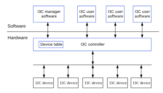
Figure : I3C block diagram
The main features of the I3C architecture are as follows:- I3C controller driver software: software-privileged entity, capable of enumeration and bus configuration.
- I3C client software: software entities that use the I3C bus for read/write to devices.
I3C packet frame structure
A frame begins with START, command (8), data (8), transition (1), and STOP.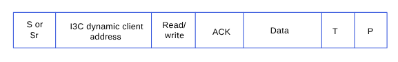
Figure : I3C packet frame
Where,- ACK: Acknowledge (SDA low)
- S: Start condition
- Sr: Repeat start condition
- P: Stop condition
- T: Transition bit alternative to ACK/NACK
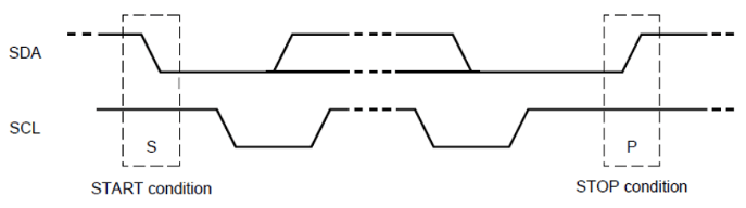
Figure : I3C sequence
I3C bus initialization
The I3C bus initialization procedure is as follows:- The I3C controller driver software initializes the I3C controller (firmware and configuration settings).
- The I3C controller driver software reads the I3C configuration and the device database, including:
- List of I2C static address devices.
- List of I3C static address devices.
- List of expected I3C dynamic devices: vendor ID, device ID, predefined dynamic address, and associated drivers.
- Optional hot-join allowed devices (vendor ID, device ID, and predefined address).
- Using the I3C controller software, the driver enumerates the devices on the bus (set local addresses).
- The I3C controller driver software writes an I3C controller with the required devices and the bus characteristic information:
- Operation frequency
- Pure/legacy I2C mode
- SDR/HDR enable/disable (and types)
- IBI capable devices and expected data bytes
- The I3C client software stack receives the following information about the I3C configuration and device database.
- List of I2C, static address devices.
- List of I3C, static address devices.
- List of expected I3C dynamic devices: vendor ID, device ID, predefined dynamic address, and associated drivers.
- Optional hot-join allowed devices (vendor ID, device ID, and predefined address).
I3C features
The aDSP/SDC I3C subsystem supports the following features.- Address phase at frequency 400 kHz.
- Data phase at frequency 12,500 kHz.
- Backward compatibility with legacy I2C.
- Dynamic addressing of targets.
- Single data rate (SDR) mode.
- CCC commands according to the MIPI I3C specification
I3C interface components
I3C use cases in the aDSP/SLPI software support sensor device communication.Note: I3C doesn’t support Linux use cases.
Table : aDSP/SLPI/SDC
| File type | Description |
|---|---|
| QUP v3 serial engine configuration |
|
| Firmware configuration settings |
|
| Public APIs |
|
I3C software GPIO configuration
The I3C firmware for the QUP v3 serial engine is loaded with SSC QUP during the bootup sequence. The configuration file is present in the aDSP build. The source code path to enable the I3C configuration for a specific QUP v3 serial engine instance is/firmware/qualcomm-linux-spf-1-0_ap_standard_oem_nomodem/ADSP.HT.5.5.c8/adsp_proc/core/settings/buses/qup_fw/config/<chipset>/fw_devcfg.c and /firmware/qualcomm-linux-spf-1-0_ap_standard_oem_nomodem/ADSP.HT.5.5.c8/adsp_proc/core/settings/buses/qup_fw/config/<chipset>/fw_devcfg.xml.
Sample of SSC QUP SE0 or SE1 loaded with the I3C firmware.
/firmware/qualcomm-linux-spf-1-0_ap_standard_oem_nomodem/ADSP.HT.5.5.c8/adsp_proc/core/settings/buses/qup_common/config/<chipset>/adsp/ssc/qup_instance_mapping.c.
The default GPIO configuration can be overwritten as follows: