UART devices transmit data asynchronously. Hence, a clock signal doesn’t synchronize the output of bits from the transmitting UART to the sampling of bits by the receiving UART. Instead of a clock signal, the transmitting UART adds start and stop bits to the data packet being transferred. These bits define the beginning and end of the data packet. This way, the receiving UART is aware of when to start reading the bits. When the receiving UART detects a start bit, it starts to read the incoming bits at a specific frequency known as the baud rate.
Data transfer between two UART devices

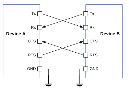
Figure : Data transfer between two UART devices

The parameters that determine successful transmission are as follows:
  • Baud rate
  • Start bit
  • Stop bit
  • Parity bit
  • Data bits
  • Flow control
The following figure shows a sample UART data packet.
UART data packet

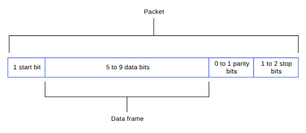
Figure : UART data packet

UART features

The following table describes the UART transfer modes for applications.

Table : UART transfer modes

SubsystemTransfer modeDescription
Linux
  • FIFO (low speed)
  • CPU DMA (high speed)
  • Supports baud rates from 300 bps up to 4 Mbps.
  • FIFO mode transfers data between its Rx/Tx buffers and system memory.
  • DMA mode transfers data between its Rx/Tx buffers and system memory. Better performance is achieved with high-speed UART drivers supporting higher baud rates and bigger data packages. For example, the Bluetooth wireless technology connectivity module.
BootFIFO
  • Rx/Tx 5 bits to 8 bits per character.
  • Supports a maximum baud rate of 115200.
aDSPFIFO
  • Rx/Tx 5 bits to 8 bits per character.
  • Supported baud rates: 115200, 230400, 460800, 921600, 1000000, 3000000, and 6000000.

UART interface components

The following table provides the paths of UART driver configurations for the different subsystems. Table : UART interface: Linux
File typeDescription
Device tree source
Pinctrl settings
Qualcomm TEE settings
  • /firmware/qualcomm-linux-spf-1-0_ap_standard_oem_nomodem/TZ.XF.5.0/trustzone_images/core/settings/buses/qup_accesscontrol/qupv3/config/<chipset>/QUPAC_Access.c
Table : UART interface: Boot (UEFI-only)
File typeDescription
QUP v3 serial engine configuration
  • /firmware/qualcomm-linux-spf-1-0_ap_standard_oem_nomodem/BOOT.MXF.1.0.c1/boot_images/boot/QcomPkg/SocPkg/<chipset>/Settings/UART/UartSettings.c
Qualcomm TEE settings
  • /firmware/qualcomm-linux-spf-1-0_ap_standard_oem_nomodem/TZ.XF.5.0/trustzone_images/core/settings/buses/qup_accesscontrol/qupv3/config/<chipset>/QUPAC_Access.c
Table : UART interface: aDSP/SLPI
File typeDescription
QUP v3 serial engine configuration
  • /firmware/qualcomm-linux-spf-1-0_ap_standard_oem_nomodem/ADSP.HT.5.5.c8/adsp_proc/core/settings/buses/qup_common/config/<chipset>/adsp/ssc/qup_devcfg.c
  • /firmware/qualcomm-linux-spf-1-0_ap_standard_oem_nomodem/ADSP.HT.5.5.c8/adsp_proc/core/settings/buses/qup_fw/config/<chipset>/fw_devcfg.c
Firmware configuration settings
  • /firmware/qualcomm-linux-spf-1-0_ap_standard_oem_nomodem/ADSP.HT.5.5.c8/adsp_proc/core/settings/buses/qup_fw/config/<chipset>/fw_devcfg.c
  • /firmware/qualcomm-linux-spf-1-0_ap_standard_oem_nomodem/ADSP.HT.5.5.c8/adsp_proc/core/settings/buses/qup_fw/config/<chipset>/fw_devcfg.xml

UART APIs

UART APIs for the following subsystems are listed in this section.

UART software device tree configuration

This section provides information on the UART device tree configuration, and documentation for the device nodes.

Linux

For information about Kernel device instances, see https://github.com/torvalds/linux/blob/master/Documentation/devicetree/bindings/serial/qcom%2Cserial-geni-qcom.yaml. For information about the UART driver files, see https://github.com/torvalds/linux/blob/master/drivers/tty/serial/qcom_geni_serial.c
uart7: serial@99c000 {
/* Manufacturer model of serial driver */
compatible = "qcom,geni-uart";
/* SE address and size */
reg = <0 0x0099c000 0 0x4000>;
/*Clocks for SE */
clocks = <&gcc GCC_QUPV3_WRAP0_S7_CLK>;
clock-names = "se";
/* pinctrl setting */
pinctrl-names = "default";
pinctrl-0 = <&qup_uart7_cts>, <&qup_uart7_rts>, <&qup_uart7_tx>, <&qup_uart7_rx>;
interrupts = <GIC_SPI 608 IRQ_TYPE_LEVEL_HIGH>;
power-domains = <&rpmhpd SC7280_CX>;
operating-points-v2 = <&qup_opp_table>;
interconnects = <&clk_virt MASTER_QUP_CORE_0 0 &clk_virt SLAVE_QUP_CORE_0 0>,
<&gem_noc MASTER_APPSS_PROC 0 &cnoc2 SLAVE_QUP_0 0>;
				interconnect-names = "qup-core", "qup-config";
/* To enable QUPV3 serial engine instance for UART protocol, change Status to OK */
				status = "disabled";
			};
		}
For configuration settings of the serial engine GPIOs, see the following DTSI files.
qup_uart7_cts: qup-uart7-cts-state {
				pins = "gpio28";
				function = "qup07";
			};

			qup_uart7_rts: qup-uart7-rts-state {
				pins = "gpio29";
				function = "qup07";
			};

			qup_uart7_tx: qup-uart7-tx-state {
				pins = "gpio30";
				function = "qup07";
			};

			qup_uart7_rx: qup-uart7-rx-state {
				pins = "gpio31";
				function = "qup07";
			};
NoteThe Qualcomm TEE configurations must be aligned in the QUPAC_Access.c file to ensure that the GPIO/QUP v3 can be used. You can access the Qualcomm TEE images at /firmware/qualcomm-linux-spf-1-0_ap_standard_oem_nomodem/TZ.XF.5.0/trustzone_images/core/settings/buses/qup_accesscontrol/qupv3/config/<chipset>/QUPAC_Access.c. Modify the required settings or see the default settings assigned for particular instances of the QUP v3 serial engine.
QUP v3 supports both 4-wire UART with flow-control enabled, and 2-wire UART without flow control enabled. The following example for Qualcomm TEE access, controls entry for both. The QUP v3 serial engine configurations to enable the UART protocol are as follows:
  • Default configuration enabled for SE7 as HS UART
    { QUPV3_0_SE7, QUPV3_PROTOCOL_UART_4W, QUPV3_MODE_FIFO, AC_HLOS, TRUE, TRUE, FALSE }, 
    
  • 2-wire UART configuration for SE5
    uart5: serial@994000 {
    compatible = "qcom,geni-uart";
    reg = <0 0x00994000 0 0x4000>;
    clocks = <&gcc GCC_QUPV3_WRAP0_S5_CLK>;
    clock-names = "se";
    pinctrl-names = "default";
    pinctrl-0 =  <&qup_uart5_tx>, <&qup_uart5_rx>;
    interrupts = <GIC_SPI 606 IRQ_TYPE_LEVEL_HIGH>;
    power-domains = <&rpmhpd SC7280_CX>;
    operating-points-v2 = <&qup_opp_table>;
    interconnects = <&clk_virt MASTER_QUP_CORE_0 0 &clk_virt SLAVE_QUP_CORE_0 0>,
        <&gem_noc MASTER_APPSS_PROC 0 &cnoc2 SLAVE_QUP_0 0>;
    interconnect-names = "qup-core", "qup-config";
    status = "disabled";
    };
    
    { QUPV3_0_SE5, QUPV3_PROTOCOL_UART_2W, QUPV3_MODE_FIFO,
    AC_HLOS, TRUE, FALSE, FALSE },
    

Boot

The QUP v3 serial engine can be configured to UART in boot using the /firmware/qualcomm-linux-spf-1-0_ap_standard_oem_nomodem/BOOT.MXF.1.0.c1/boot_images/boot/QcomPkg/SocPkg/<chipset>/Settings/UART/UartSettings.c file.
UART_PROPERTIES devices =
{
   // MAIN_PORT
   0x00994000,    // Serial Engine Base address
   0x009C0000,// qup_common base address
   0x2001c161,  // GPIO TX pin Config
   0x2000c171,  // GPIO RX Pin Config
   0,           // gpio_cts_config
   0,           // gpio_rfr_config
   0,           // clock_id_index
   (void*)0,        // bus_clock_id
   (void*)CLK_QUPV3_WRAP0_S5,     // core_clock_id
   0,          // irq number not used
   0,  //TCSR base
   0,  // TCSR offset
   0   // TCSR value

};
GPIO configuration The GPIO configuration is listed in the following table. Table : UART GPIO configuration
BitsParameters
[0:3]GPIO function
[4:13]GPIO number
[14]Direction
[15:17]Pull type
[18:21]Drive strength
You must configure each GPIO based on the following bit fields.
<!--
GPIO configuration calculation

GPIO DIR values
GPIO_INPUT = 0x0
GPIO_OUTPUT = 0x1

GPIO_PULL values
GPIO_NO_PULL = 0, /**< -- Do not specify a pull. */
GPIO_PULL_DOWN = 0x1, /**< -- Pull the GPIO down. */
GPIO_KEEPER_ENABLE = 0x2, /**< -- Keeper Enable. */
GPIO_PULL_UP = 0x3, /**< -- Pull the GPIO up. */

GPIO_DRV_STRENGTH values
GPIO_2P0MA = 0, /**< -- Specify a 2 mA drive. */
GPIO_4P0MA = 0x1, /**< -- Specify a 4 mA drive. */
GPIO_6P0MA = 0x2, /**< -- Specify a 6 mA drive. */
GPIO_8P0MA = 0x3, /**< -- Specify a 8 mA drive. */

GPIO_FUNC_SELECT_Value
GPIO_FS_VAL =0, //Specifies GPIO function

GPIO_FS_VAL =0X1, //Specify NON GPIO function( UART/SPI/I2C)
	
GPIO configuration = (GPIO_NUM & 0xFF) << 0x10 |
(GPIO_FS_VAL & 0xF) << 0xC |
(GPIO_DRV_STRENGTH & 0xF) << 0x8 |
(GPIO_PULL & 0xF) << 0x4 |
(GPIO_DIR & 0xF)

-->
/*
| RESERVED | GPIO NUM | DRIVE | FUNC | PULL | DIR |
-------------------------------------------------------------------------
| 0000 | 0000 | 0001 | 1110 | 0001 | 0001 | 0010 | 0001 |
-------------------------------------------------------------------------
*/

aDSP

The firmware loads SSC QUP during the bootup sequence of the aDSP subsystem. Hence, the configuration file is present in the aDSP build at /firmware/qualcomm-linux-spf-1-0_ap_standard_oem_nomodem/ADSP.HT.5.5.c8/adsp_proc/core/settings/buses/qup_fw/config/<chipset>/fw_devcfg.c. The following configuration is a sample of SSC QUP SE5/6 loaded with the UART firmware in the FIFO mode.
                   offset,        protocol,   mode,  load_fw, dfs_mode
se_cfg se0_cfg = { 0x80000, SE_PROTOCOL_I3C,    GSI,     TRUE, TRUE  };
se_cfg se1_cfg = { 0x84000, SE_PROTOCOL_I2C,    GSI,     TRUE, TRUE  };
se_cfg se2_cfg = { 0x88000, SE_PROTOCOL_I2C,    GSI,     TRUE, TRUE  };
se_cfg se3_cfg = { 0x8C000, SE_PROTOCOL_I2C,    GSI,     FALSE, TRUE  };
se_cfg se4_cfg = { 0x90000, SE_PROTOCOL_SPI,    GSI,     TRUE, TRUE };
se_cfg se5_cfg = { 0x94000, SE_PROTOCOL_UART,   FIFO,    TRUE,FALSE };
se_cfg se6_cfg = { 0x98000, SE_PROTOCOL_UART,   FIFO,    TRUE,FALSE  };
GPIO configuration: Each serial engine in the QUP common driver is configured with the default GPIO configuration per protocol. The QUP v3 common driver picks the GPIO configuration according to the protocol loaded in the serial engine from /firmware/qualcomm-linux-spf-1-0_ap_standard_oem_nomodem/ADSP.HT.5.5.c8/adsp_proc/core/settings/buses/qup_common/config/<chipset>/adsp/ssc/qup_instance_mapping.c. The default GPIO configuration can be overwritten as follows.
{      .instance_id          =  6 ,         //Instance ID
        .qup              =  QUP_SSC,    //QUP Type
        .se_index         =  5,          //SE ID
        .se_data          =  NULL,       //devcfg_map
        .protocol_io_cfg  =  {
                                TLMM_MAP(TLMM_GPIO_KEEPER ,TLMM_GPIO_2MA,TLMM_GPIO_KEEPER ),              //SLEEP CFG
                                TLMM_MAP(TLMM_GPIO_NO_PULL,TLMM_GPIO_6MA,TLMM_GPIO_KEEPER ),              //SPI CFG
                                TLMM_MAP(TLMM_GPIO_NO_PULL,TLMM_GPIO_2MA,TLMM_GPIO_NO_PULL),              //UART CFG
                                TLMM_MAP(TLMM_GPIO_PULL_UP,TLMM_GPIO_2MA,TLMM_GPIO_NO_PULL),              //I2C CFG
                                TLMM_MAP(TLMM_GPIO_PULL_UP,TLMM_GPIO_2MA,TLMM_GPIO_KEEPER )               //I3C CFG
                             },
        .se_exclusive     =  TRUE,
}
TLMM_MAP is a macro to initialize the active and sleep state GPIO configurations. For example, sample usage of the TLMM_MAP macro.
TLMM_MAP (active state pull type, drive strength, sleep state pull type)

UART tools

This section provides information on various test tools and methods for the UART serial interface driver to confirm the UART data transfers.

Linux

For more details, see https://docs.kernel.org/admin-guide/serial-console.html.

Enable UART in kernel

This section provides information on how to enable UART in the kernel.

Linux

The following driver kernel configurations are required to support the UART interface. Enable the following kernel configurations.
  • CONFIG_QCOM_GENI_SE=y
  • CONFIG_SERIAL_QCOM_GENI=y
To enable a serial node for the loopback validation, apply the following patch in the /arch/arm64/boot/dts/qcom/<chipset>.dtsi file.
--- a/arch/arm64/boot/dts/qcom/<chipset>.dtsi
+++ b/arch/arm64/boot/dts/qcom/<chipset>.dtsi
@@ -70,6 +70,7 @@
 		spi13 = &spi13;
 		spi14 = &spi14;
 		spi15 = &spi15;
+		serial1 = &uart7;
}; 


+
+&uart7 {
+	status = "ok";
+}; 
NoteYou should compile the kernel configuration and device tree changes. After compilation, you can load the images to the device to verify the interface. For information about interface verification, see the Verify UART interface section.

Boot/aDSP

For customizations, see the UART software device tree configuration section.

UART customization

For information about customizing UART software, see QUP v3 access control customization.

Verify UART interface

This section describes the validation procedure for the UART drivers, and the test results for the Qualcomm drivers.

Linux

To enable the UART nodes, do the following and compile the kernel configuration.
  1. To change the UART status to OK and aliases to the specific UART node, edit the following DTSI files.
    NoteEnable the SSH shell or use the ADB shell to run the commands and display the output in the SSH shell (console) window. For more information about how to run SSH, see the Use SSH section.
    aliases {
    i2c0 = &i2c0;
    spi15 = &spi15;
    ++serial1 = &uart7;
    };
    uart7: serial@99c000 {
    compatible = "qcom,geni-uart";
    reg = <0 0x0099c000 0 0x4000>;
    clocks = <&gcc GCC_QUPV3_WRAP0_S7_CLK>;
    clock-names = "se";
    pinctrl-names = "default";
    pinctrl-0 = <&qup_uart7_cts>, <&qup_uart7_rts>, <&qup_uart7_tx>,
    <&qup_uart7_rx>;
    interrupts = <GIC_SPI 608 IRQ_TYPE_LEVEL_HIGH>;
    power-domains = <&rpmhpd SC7280_CX>;
    operating-points-v2 = <&qup_opp_table>;
    interconnects = <&clk_virt MASTER_QUP_CORE_0 0 &clk_virt SLAVE_QUP_CORE_0
    0>,
    <&gem_noc MASTER_APPSS_PROC 0 &cnoc2 SLAVE_QUP_0 0>;
    interconnect-names = "qup-core", "qup-config";
    ++status = "ok";
    };
    
  2. Disable the if condition in the qcom_geni_serial.c at https://github.com/torvalds/linux/blob/master/drivers/tty/serial/qcom_geni_serial.c file for the loopback test.
    //if (mctrl & TIOCM_LOOP) // Disabling the if condition for loopback test
    port->loopback = RX_TX_CTS_RTS_SORTED;
    
To validate the QUP v3 UART registration functionality in the Linux kernel, ensure that the UART is correctly registered with the TTY stack.
  1. Disable the UART default use case in the following DTSI files.
    bluetooth: bluetooth {
           ++      status = "disabled";
    
    The following output is displayed.
    ls /dev/ttyHS1
    /dev/ttyHS1
    dmesg | grep ttyH
    [    3.355487] 99c000.serial: ttyHS1 at MMIO 0x99c000 (irq = 137, base_baud = 0) is a MSM
    
  2. To verify the UART driver, do the following:
    1. Open the SSH shell in permissive mode or use the ADB shell.
    2. Register the UART.
      ls /dev/ttyHS*
      
      The following is a sample output.
      ls /dev/ttyHS*
      /dev/ttyHS1
      
      Map the ttyHS1 port according to the aliases added for the serial1 = &uart7 and enable the serial engine.
The UART devices registered in the kernel are listed. The UART driver follows the test sequence to enable loopback. After enabling the UART node in the DUT, run the following commands to verify that the UART instance is enabled in the DTSI file.
NoteOpen two SSH shells or use the ADB shell to write and read the data for the UART loopback. For more information about how to run SSH, see the Use SSH section.
  1. Open the SSH shell in permissive mode or use the ADB shell.
  2. Transfer data with the echo command.
    echo "This Document Is Very Much Helpful" > /dev/ttyHS1
    
  3. Read data in the UART device node.
    cat /dev/ttyHS1
    

Debug UART issues

This section provides information about enabling the debug logs in the UART software driver.

Linux

UART driver logging is enabled through the dynamic debugging method. Enable CONFIG_DYNAMIC_DEBUG in <workspace_path_of_LINUX_kernel_image>/sources/kernel/kernel_platform/kernel/arch/arm64/configs/qcom_defconfig to support the dynamic debugging for kernel drivers. To enable and view the UART driver logs in the kernel logs (dmesg), run the following command.
mount -t debugfs none /sys/kernel/debug
echo -n "file qcom_geni_serial.c +p" > /sys/kernel/debug/dynamic_debug/control
echo -n "file qcom-geni-se.c +p" > /sys/kernel/debug/dynamic_debug/control
echo -n "file serial_core.c +p" > /sys/kernel/debug/dynamic_debug/control
echo -n "file gpi.c +p" > /sys/kernel/debug/dynamic_debug/control

UART examples

For information about the upstream device tree reference, see the following DTSI files. For information about device-tree node for the Qualcomm Linux hardware SoCs, see the following DTSI files.